Jump to content
LIMITED TIME OFFER: Use code 10YEARS10 to get 10% off your Appliantology membership. Click here for more ×
Click here to check out our structured, online appliance repair training courses for rookies and experienced techs.

FAQs | Repair Videos | Academy | Newsletter | Contact


When the Tech Sheet Lies...


Son of Samurai

2,596 views

Tell me what's wrong with this picture:

3B958F3B-8C73-4BCE-A19D-C21BB6EAD603.jpeg.65a0bf327a3ba79ae422f3f0b159e464.jpeg

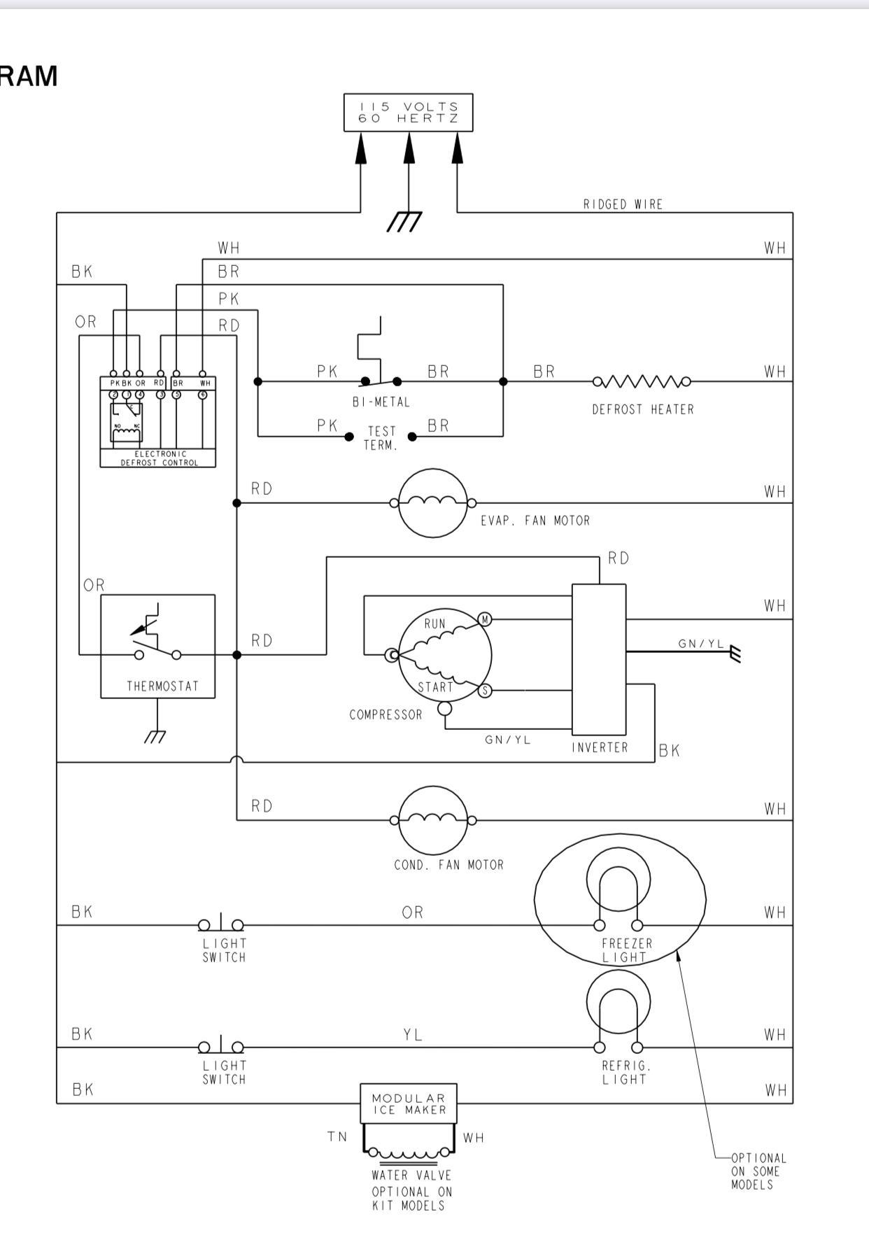
No, your eyes are not playing tricks on you -- that schematic really is showing a split-phase compressor being run by an inverter board.

If you're sitting there sputtering and foaming at the mouth in disbelief, thinking, "That can't possibly be correct," then congrats! You had the correct reaction. What this diagram is showing simply can't line up with reality. Split-phase motors are never run using inverter boards -- the very idea is nonsensical. This particular model does indeed have an inverter board, but as you might expect, the compressor is in actuality a BLDC motor.

What's going on here is nothing more than a bit of shoddy work from whoever put this tech sheet together (thank you, Whirlpool).  And it extends beyond just the schematic:

Screen Shot 2019-11-12 at 8.14.46 PM.png

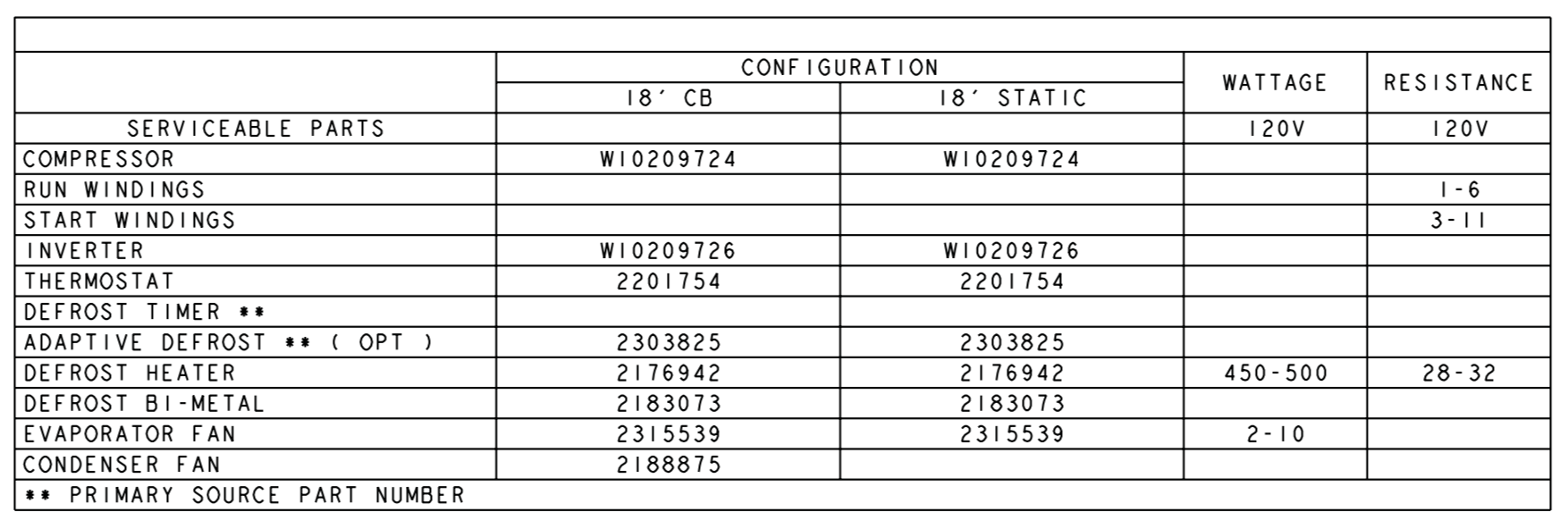
They even give winding specs for the compressor as if it's a split-phase motor! But if you do a resistance measurement across the coils of that motor, you'll see that they're all the same resistance, like you would expect for a BLDC motor.

We as techs rely on technical documentation to do our job. We need the schematics, we need the specs. But we also need to stay watchful and foster a functional understanding of the technology we're working with, because sometimes you need to call BS when the manufacturers give you bad info.

Want to get that functional understanding of the many technologies you'll encounter on your journey through appliance repair? Come get that at Master Samurai Tech. Also, if you're a premium tech member here at Appliantology, click here to give our webinar recordings a peek.

  • Like 4

6 Comments


Recommended Comments

Thank you for the information.

I noticed in the schematic is that both light switches are drawn in the NC Normally Closed position. The lights would be on.

Link to comment

They probably had a college student intern draw the schematic without any oversight by more experienced engineers...

Charlie

Link to comment
fillthebarman

Posted

i was working on a ge dryer yesterday and the wire colors were wrong.

Link to comment

How would the inverter gets the PWM signal to run the compressor? Correct me if I'm wrong, but I see Hot (black), Neutral (white), Ground (green/yellow) wires coming in to the inverter. What's that single Red wire for? Is that the dc signal wire? But it looks like that red wire is also running parallel to the condenser and evap fan motors providing the hot ac line to them from the defrost control. I'm kinda confused. 

Link to comment
  • Team Samurai
Son of Samurai

Posted

That's an excellent question, @Kerenza -- good spot!

You're correct that there's no DC wire going to that inverter board, which is very odd. If that's really how it's wired, then it must be designed to only run at a single speed. Why use an inverter and BLDC motor if that's the case? Beats me.

The other possibility is that it's yet another error in the tech sheet. Once you see an egregious mistake like showing the wrong compressor, everything else in the document becomes suspect. Who knows what else on the schematic is wrong? As far as I'm concerned, it's not a trustworthy or useful tech sheet anymore, since we have to second guess everything that it shows.

It's unfortunate when the manufacturers are this sloppy, but it happens. It's up to us as the techs to be observant, discerning, and knowledgable enough to recognize when the manufacturer has messed up.

Link to comment
×
×
  • Create New...