
Identifying Sensing Wires in Schematics

Entry posted by Son of Samurai
2,971 views
Have you ever noticed some connections on a schematic that just look plain unnecessary? Take a look at CN1 on this diagram.
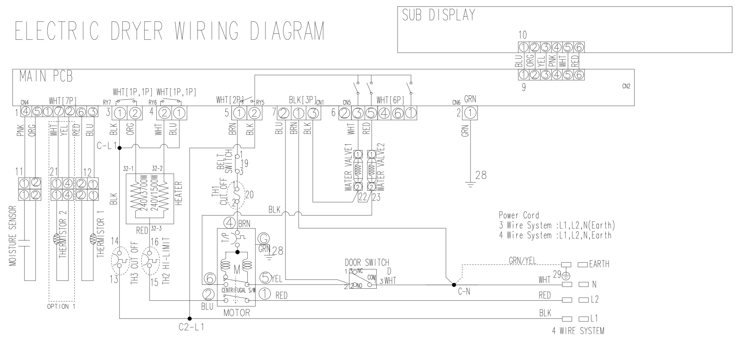
If you trace out those three wires, it may not be immediately obvious to you what the point of them is. Let's look at each connection individually, starting with pin 1.
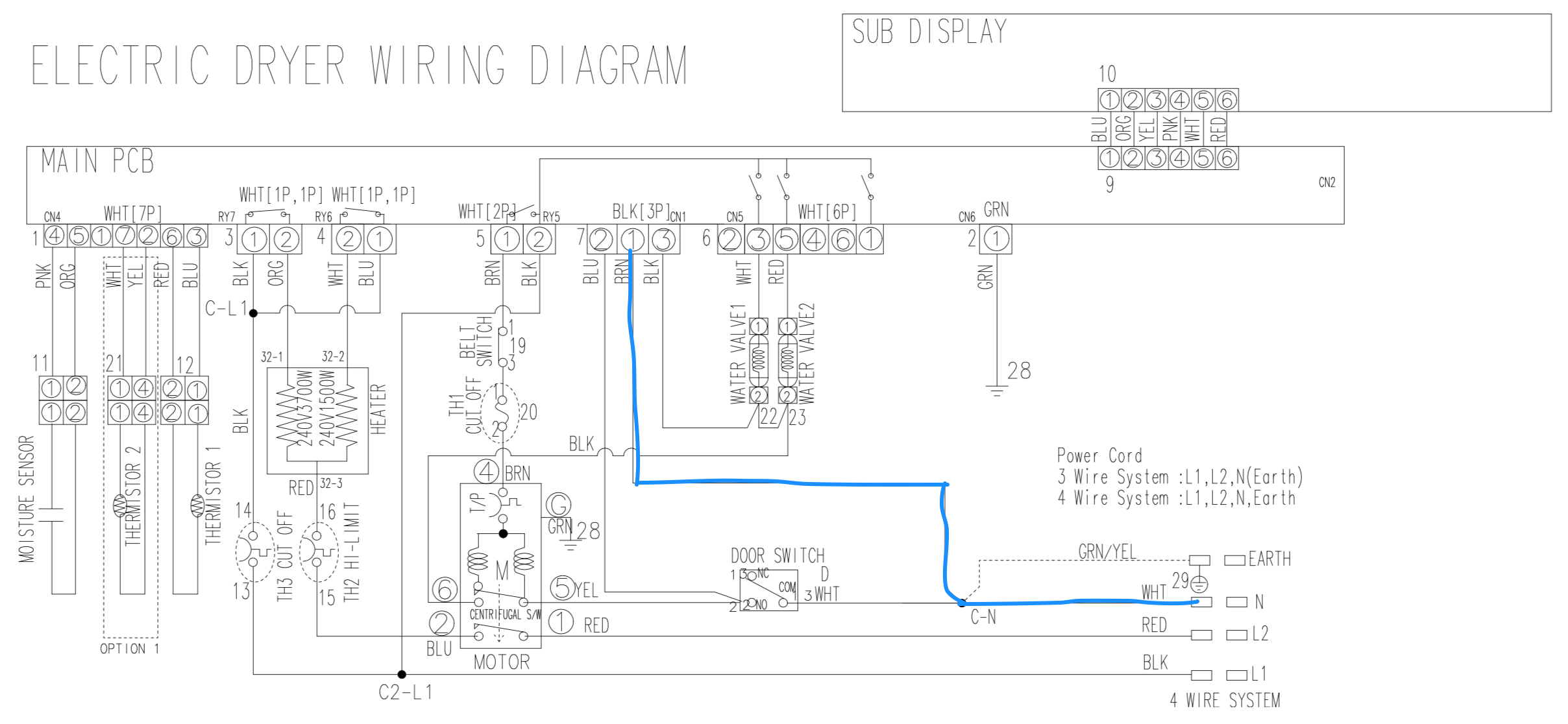
Well that looks pretty standard. It takes a direct path to neutral with no components in between. Nothing unusual about that -- the board needs its own neutral supply in order to run, after all. What about pin 2?
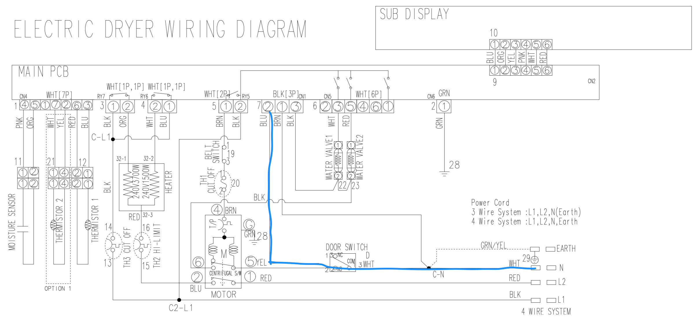
Interesting -- again, it goes straight to neutral, but it has to pass through the door switch to get there. Let's see what's going on at pin 3...

Wow, that one took us for quite a ride! Not only does pin three join up with the neutral wire for the water valves, but it also passes through the centrifugal switch and the door switch.
So that's an entire connection of nothing but redundant neutral supplies. What gives?
Well, we were right about pin 1 being the neutral supply for the board. But as for pins 2 and 3, those are both sensing wires. The board's logic is able to detect the presence or absence of a good neutral, and so by having these seemingly "redundant" neutral connections, engineers have enabled the board to detect the state of a couple components.
Look at pin 2 again. Since it passes through the door switch, the board will be able to tell when the door switch is open or closed based on the presence or absence of neutral. This lets the algorithm both make decisions based on the state of the switch and throw error codes when it thinks there's a problem with the switch.
Similarly, since the wire from pin 3 passes through the centrifugal switch, that lets the board know the state of the switch and by extension the drive motor. If that switch is open when the board expects the motor to be running, it will probably throw a no spin error.
We studied a ton of cool circuit configurations like this in this awesome webinar on Samsung dryer troubleshooting, available only to premium members at Appliantology.
-
.png) 8
8


0 Comments
Recommended Comments
There are no comments to display.