
EEPs: What they are and how to use them

Entry posted by Son of Samurai
3,268 views
When you need to test a component, do you always need to just resign yourself to tearing apart the appliance until you reach it? Or is that a waste of time and energy (not to mention unnecessary liability), when you could be working smarter, not harder?
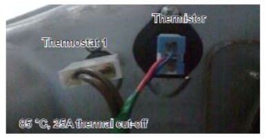
Let's say you're working on a Samsung dryer, and you want to measure the thermistor. You know the ohm spec (unfortunately they don't give you voltage drop), so all you need to do is get your meter probes on it so that you can compare. Is your next step to disassemble the machine until you can find the thermistor's harness, unplug it, and do your measurement?
Or is there a way that wouldn't require you to take the machine apart and spend time rolling around on the customer's floor? Well, let's crack out the schematic and put our big brains to work.
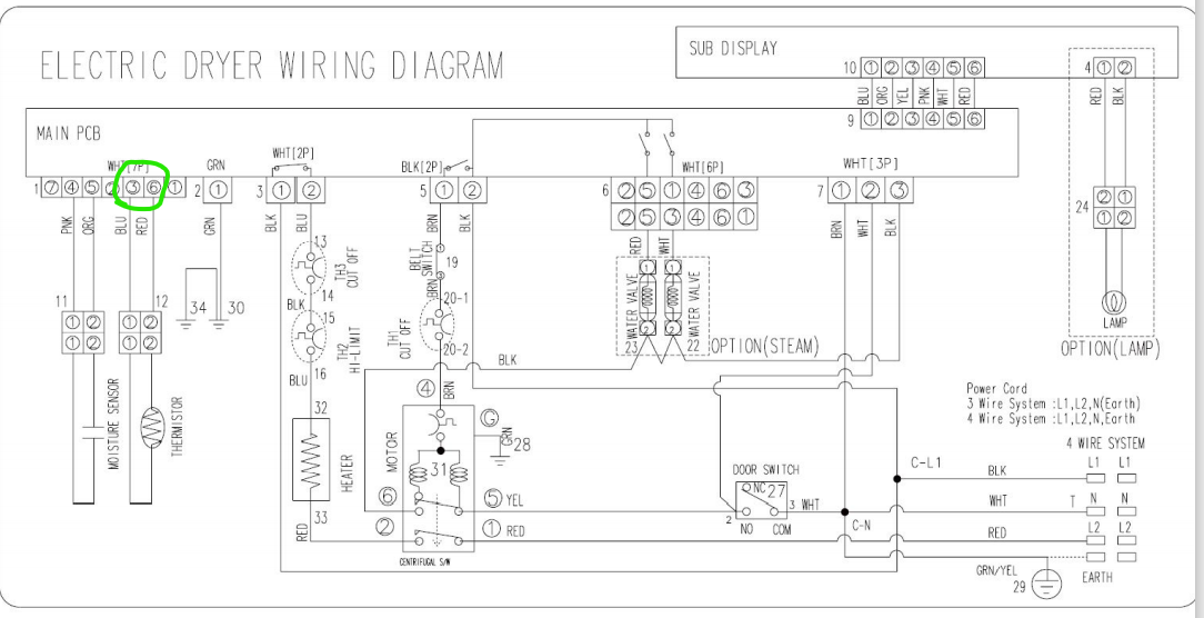
Aha! That didn't take too long to spot. See the thermistor? And see the area directly connected to it that I've circled, right where it connects to the main control? That's our golden ticket right there. That's showing that there's a harness connector on the control that connects directly to both ends of the thermistor, with no other components between.
We have located what's called electrically equivalent points, or EEPs. These are testing points that are electrically identical to physically putting your probes on the thermistor itself. Why does this matter? Because in almost every appliance, the control is one of the easiest components to access. And by doing your test from the control, you're eliminating unnecessary disassembly, which means saved time, which means saved money.
That was an easy one. What if you wanted to check one of those steam water valves (let's say the one on the right labelled 22, for simplicity). How would you test that?
The PCM way would be to take apart the dryer until you get to the valve, then do a braindead ohms check on the coil. Let's see how you would do this as a real tech.
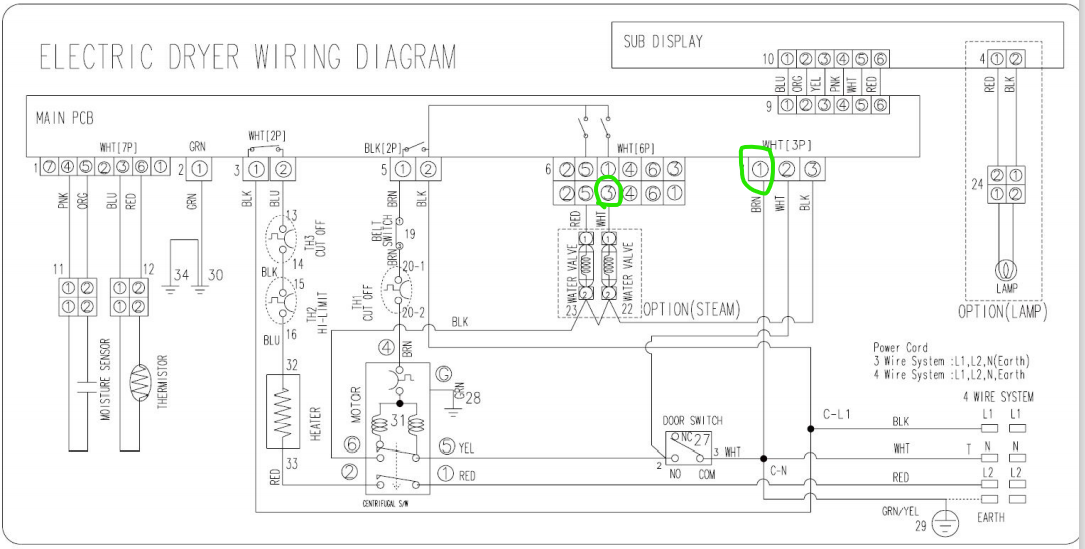
These EEPs are a little less obvious than those for the thermistor, and (very important) they are not ohms test points. These are the test points for doing a voltage measurement. Voltage measurements are the preferred test over ohms, whenever possible, because they're more reliable. Plus, it's the only test possible here if we want to troubleshoot from the control board.
Pin 3 on connector 6 is the voltage supply to the valve. That's where we should have a good 120 VAC coming from the control board. Pin 1 on connector 7, on the other hand, is a known good neutral. That's our reference for this test. With one, simple voltage measurement, we can confirm whether or not the control is sending a good 120 VAC to the valve. No extra disassembly needed.
Enterprising Appliantologists might be wondering about the neutral side of the valve's power supply, and they'd be right to do so! There are two components in the neutral for the water valves -- the centrifugal switch and the door switch. How do you test those without disassembly? Do we finally have to resign ourselves to taking everything apart?
Not at all! There's one more simple voltage test we can do to determine if we have a good neutral to that valve.
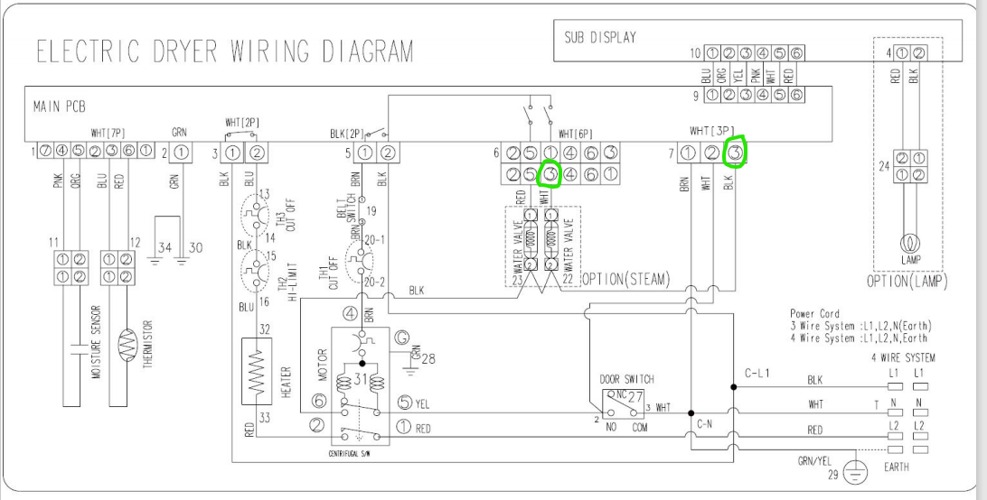
One lead is in the same place as before (Con 6 pin 3), but now we've shifted the one in connector 7 over to pin 3. If we're doing this test, we've confirmed that we have a good voltage supply. So now we're using that as our reference for checking neutral. Very important that you use a loading meter for this test!
If we again read 120 VAC, we have confirmed that we have a good neutral all the way up to Con 7 pin 3, which means that both the centrifugal switch and the door switch are properly closed.
Once you've confirmed a good power supply, that leaves only the valve as the culprit. Now, with complete confidence, we can get the part and install it. No fumbling around, no unnecessary disassembly to reach parts for testing.
All in a day's work for a Master Samurai Tech! Want to learn more about how to troubleshoot using EEPs like a real tech? Click here to check out the Core appliance repair training course over at the MST Academy.
-
.png) 2
2


5 Comments
Recommended Comments