Jump to content
LIMITED TIME OFFER: Use code 10YEARS10 to get 10% off your Appliantology membership. Click here for more ×
Click here to check out this guide

FAQs | Repair Videos | Academy | Newsletter | Contact


Appliance Repair Tech Tips

  • entries
    219
  • comments
    728
  • views
    149,084

How Does this 120 VDC Ice Auger Motor Work?


Son of Samurai

3,878 views

We've got an interesting one for you today -- take a look at the "IDI Motor" in this schematic:

Screenshot 2021-05-06 011910.png

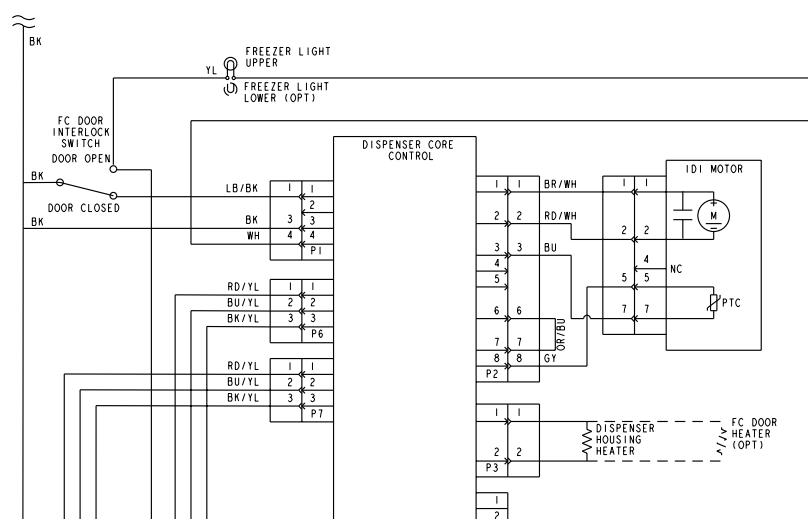
That's the ice dispenser auger motor in this fridge, and there are a couple interesting things to figure out about it. First, what's the deal with its power supply? If you look at the label on the motor, you'll notice that it says:

Whirlpool_IDI_augur_motor_2252130_Label.png.e021699719c7b3d2e60953d160a5ae66.png

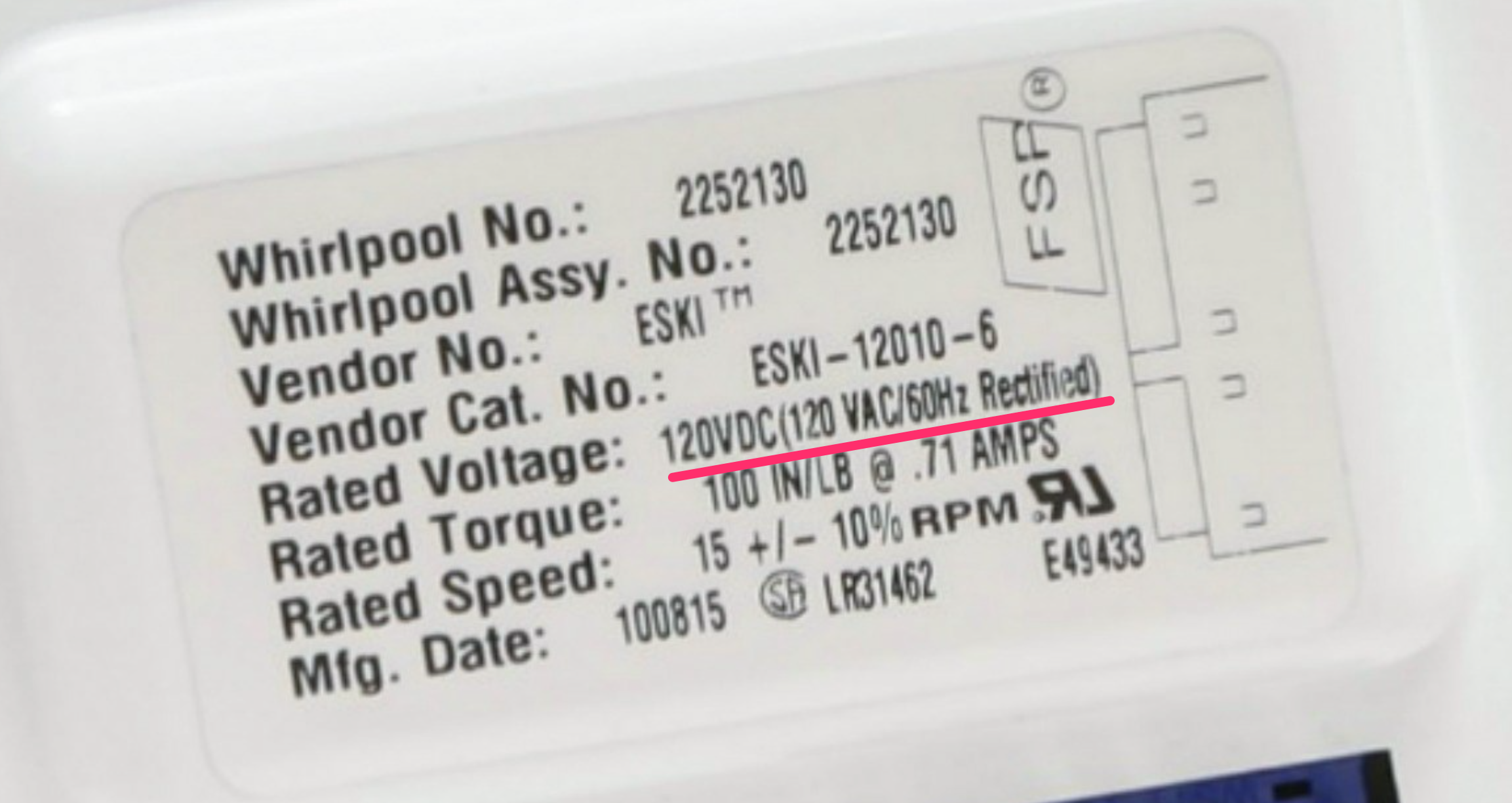
So that's a 120 VDC motor. How does that work?

A quick look through the documentation tells us that this motor is designed to run in two different directions, depending on the polarity of the DC power applied to it. Note #3 below shows this:

Whirlpool_GS6NBEXRL00_Refrigerator_Wiring_Diagram_Notes.png.2135e167e32b437e88aa046f09ef7f77.png

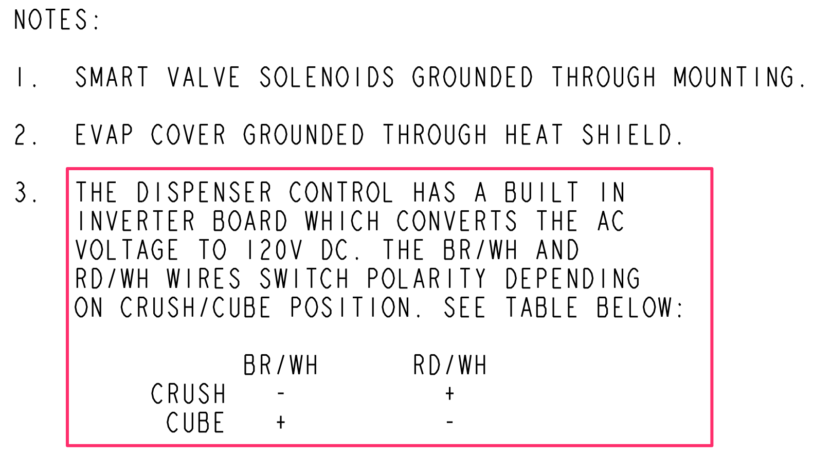
Did you catch the mistake in Whirlpool's documentation here? They talk about an inverter converting AC to DC, but that's actually the opposite of what an inverter does. The label on the motor has it right: you need a rectifier to change AC to DC.

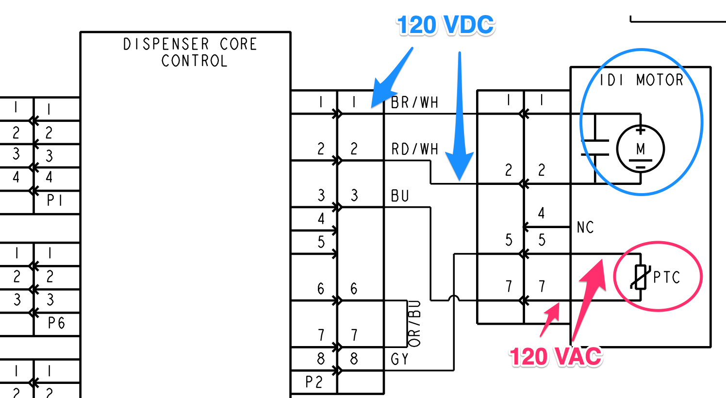
Another question -- we can see that there's a PTC connected to the dispenser control board. We might expect to see something like this as a safety in the motor's circuit, but it doesn't appear to be in the motor's circuit. Rather, it has its own connections to the dispenser control. What's going on here?

There are no notes giving us the answer on this one, but if we employ some of our own circuit know-how, we can figure out what the purpose of that PTC must be.

Before the board rectifies its 120 VAC supply into 120 VDC for powering the motor, it first sends it through the PTC. Why? As a safety device. If the IDI motor jams during operation, it will cause excessive current that will cause the PTC to open. That cuts off the 120 VAC before it even gets to become 120 VDC, which prevents the jammed motor from receiving power.

wiringsheet-2303927-reva_pdf.png.f4a0a90050776336ea6a2c2c25aff663.png

Want to learn how to read schematics, understand circuits, and troubleshoot with confidence? Click here to check out our online Core Appliance Repair training course at the Master Samurai Tech Academy.

  • Like 5

8 Comments


Recommended Comments

Excellent..I thought that "120 VDC" was a mistake in documentation.

  • Like 1
Link to comment

Hi

Is having a PTC device on an ice maker control board usually the case for protection to a motor?   Have not gotten to Module 4 of Refrigerator Principles of Operation yet.

Link to comment
  • Team Samurai
Samurai Appliance Repair Man

Posted

1 hour ago, Dav79 said:

Is having a PTC device on an ice maker control board usually the case for protection to a motor? 

This is a unique application of the PTC thermistors in ice makers. But PTCs are commonly used to control another motor you're familiar with: the compressor motor start winding. 

The key in this case is understanding how PTCs work and, based on that, what its function must be in this circuit. PTC= positive temperature coefficient. This refers to the PTC resistance vs. temperature. As its temperature increases, so does its resistance.

PTC thermistors are designed so that their internal resistance goes very high (almost but not quite open) very fast. So they can act as a switch, as in this case, or a heat source (such as in wax motors used in washer door lock assemblies). 

Knowing this about PTC thermistor technology and its application is what enables you to reason through the function of the PTC in the circuit and therefore understand how the motor circuit is supposed to function. This is essential because if you don't understand how something is supposed to work, you can't troubleshoot it when it's not working. 

  • Like 6
  • Thanks 1
Link to comment

This is exactly the problem I am working with now... does this example mean a technician (myself) would see 120VDC and 120VAC in the two points you highlight when the dispense ice is depressed? (Beginner here)... Thanks very much, learning so much...


David

Link to comment
  • Team Samurai
Son of Samurai

Posted

7 hours ago, dfphoto said:

This is exactly the problem I am working with now... does this example mean a technician (myself) would see 120VDC and 120VAC in the two points you highlight when the dispense ice is depressed? (Beginner here)... Thanks very much, learning so much...


David

Yes, you would read 120 VDC across the motor when the ice dispenser is actuated.

Similarly, you would read 120 VAC present in the PTC's circuit. Note that I don't say that you would read 120 VAC across the PTC. That would only happen if the PTC has gone open, which would prevent power from being sent to the motor. But if you put one lead on a point in the PTC's circuit, and another on a valid Neutral, you would measure 120 VAC.

  • Like 2
Link to comment

Thank you for that clarification... I am learning a lot from you guys! Going tomorrow hope to get this ice augur issue resolved...

  • Like 1
Link to comment

Hi SOS, may I ask a beginner question. The Sensei  preaches using LowZ on AC 120V and I'm wondering on this type of situation where the PTC is taking the 120AC and the motor is using 120DC would I use my meter in LowZ when I check the DC Voltage or switch to the DC setting. My meter (Klein MM720) has an auto LowZ detection mode for AC and DC. I'm thinking no, but thought I should ask before I blow up something.

Thanks, David

Link to comment
  • Team Samurai
Son of Samurai

Posted

12 hours ago, dfphoto said:

Hi SOS, may I ask a beginner question. The Sensei  preaches using LowZ on AC 120V and I'm wondering on this type of situation where the PTC is taking the 120AC and the motor is using 120DC would I use my meter in LowZ when I check the DC Voltage or switch to the DC setting. My meter (Klein MM720) has an auto LowZ detection mode for AC and DC. I'm thinking no, but thought I should ask before I blow up something.

Thanks, David

Great question, David! Yes, you should absolutely use your LoZ setting for any working voltage — that is, voltage that’s driving current through a load. Doesn’t matter if it’s AC or DC.

The situation where you don’t want to use a loading meter is when you’re measuring data lines. That voltage isn’t meant to have a load placed on it.

  • Like 1
Link to comment
×
×
  • Create New...