Jump to content
LIMITED TIME OFFER: Use code 10YEARS10 to get 10% off your Appliantology membership. Click here for more ×
Click here to check out this guide

FAQs | Repair Videos | Academy | Newsletter | Contact


Appliance Repair Tech Tips

  • entries
    220
  • comments
    728
  • views
    149,566

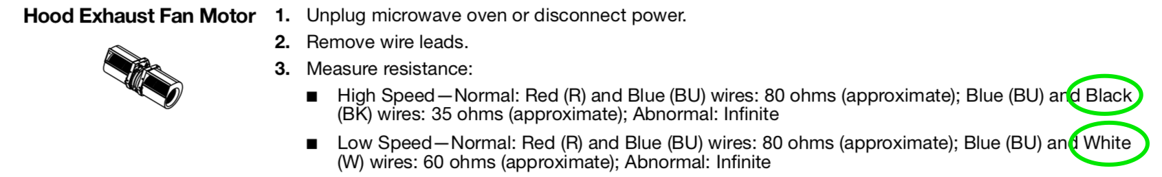
How Many Speeds Does This Fan Motor Have?


Son of Samurai

2,920 views

Let's look at a seemingly simple load that has more going on than you would think: a multi-speed hood fan in a microwave. The questions we want to answer are: how many speeds does this fan have and how does it achieve those speeds?

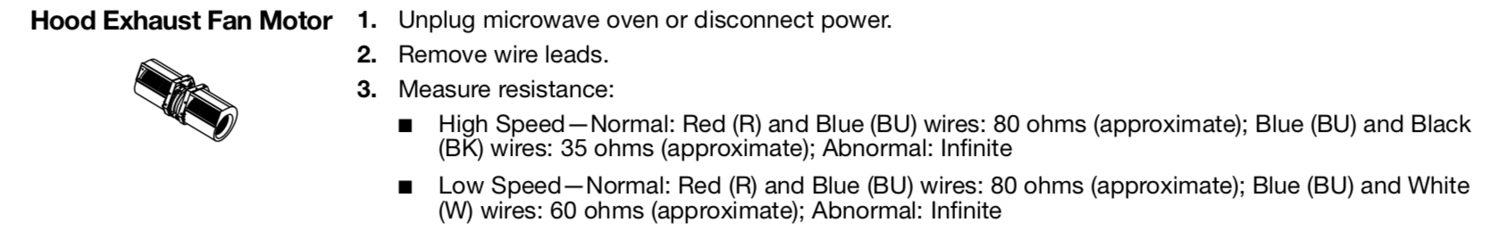
If you look at the spec block for the motor, the answer to the first question seems easy -- looks like it's a simple two-speed motor.

Screen Shot 2023-01-18 at 5.51.43 PM.png

But when you look elsewhere in the tech sheet, you find this voltage table that seems to state you have four speeds. (By the way, there are a number of erroneous values in this voltage table, so we're not going to use it as part of our case study -- but if you want extra credit, you can identify the nonsensical values).

Screen Shot 2023-01-18 at 5.52.07 PM.png

And when you then look at the schematic, you see that you have a number of components in the circuit for the hood fan -- two more relays than you would expect, and a resistor.

Screen_Shot_2023-01-18_at_5_51_22_PM.png

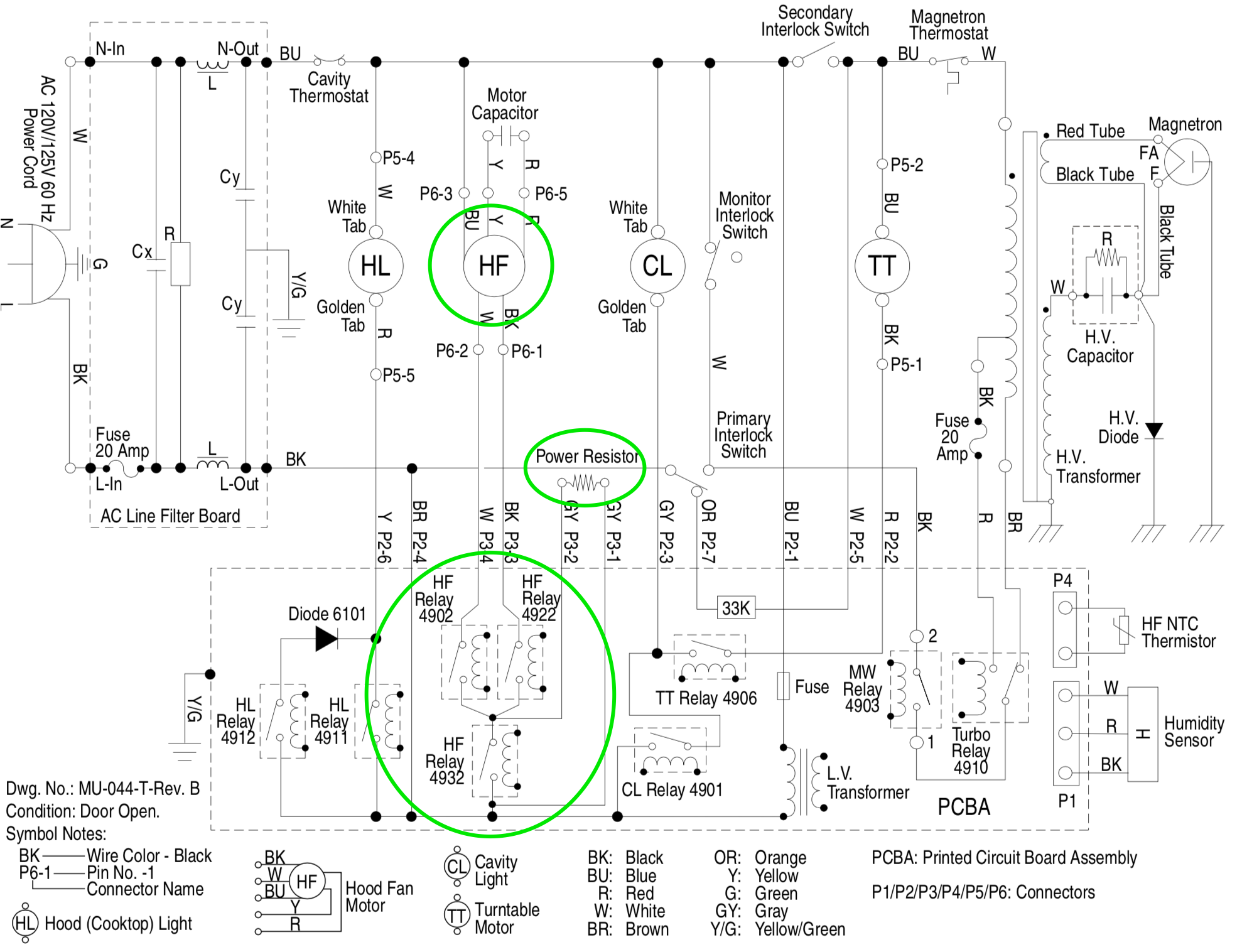
Let's cohere all of this information along with our functional understanding of circuits to puzzle out what's going on.

We know that the motor has two different speed windings from the spec block. And we know from the wire colors given there that P6-1 is the pin for the high speed winding, P6-2 for the low speed winding, and P6-3 for common.

Screen_Shot_2023-01-18_at_5_51_43_PM.png

We can now look at the schematic again and consider what those relays are doing. Relays 4902 and 4922 are pretty clear: that's how the control selects which motor winding to energize: high or low. But what about Relay 4932?

Well, the only thing Relay 4932 could be doing is shunting the power resistor. So when 4932 is open, the power resistor is in series with the rest of the circuit, but when it's closed, no current flows through the power resistor.

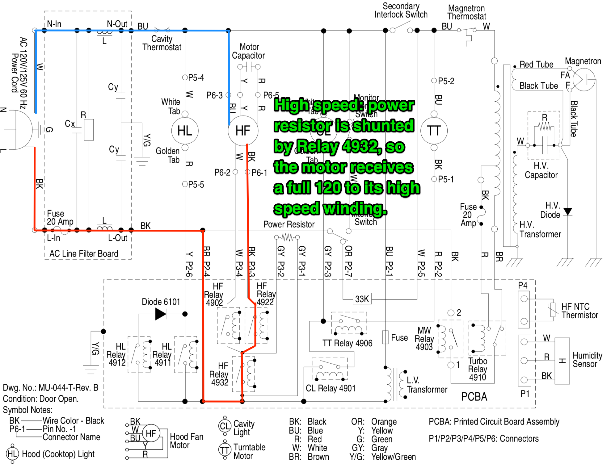
And now we have the full picture of what they're doing: by opening and closing certain ones of those three relays below the fan motor, the control can control not only which speed winding gets power, but whether that winding is receiving a full 120 VAC or not.

To demonstrate, here's a markup of high speed:

Screen_Shot_2023-01-18_at_5_51_22_PM-2.png

And now medium-high speed:

Screen_Shot_2023-01-18_at_5_51_22_PM-4.png

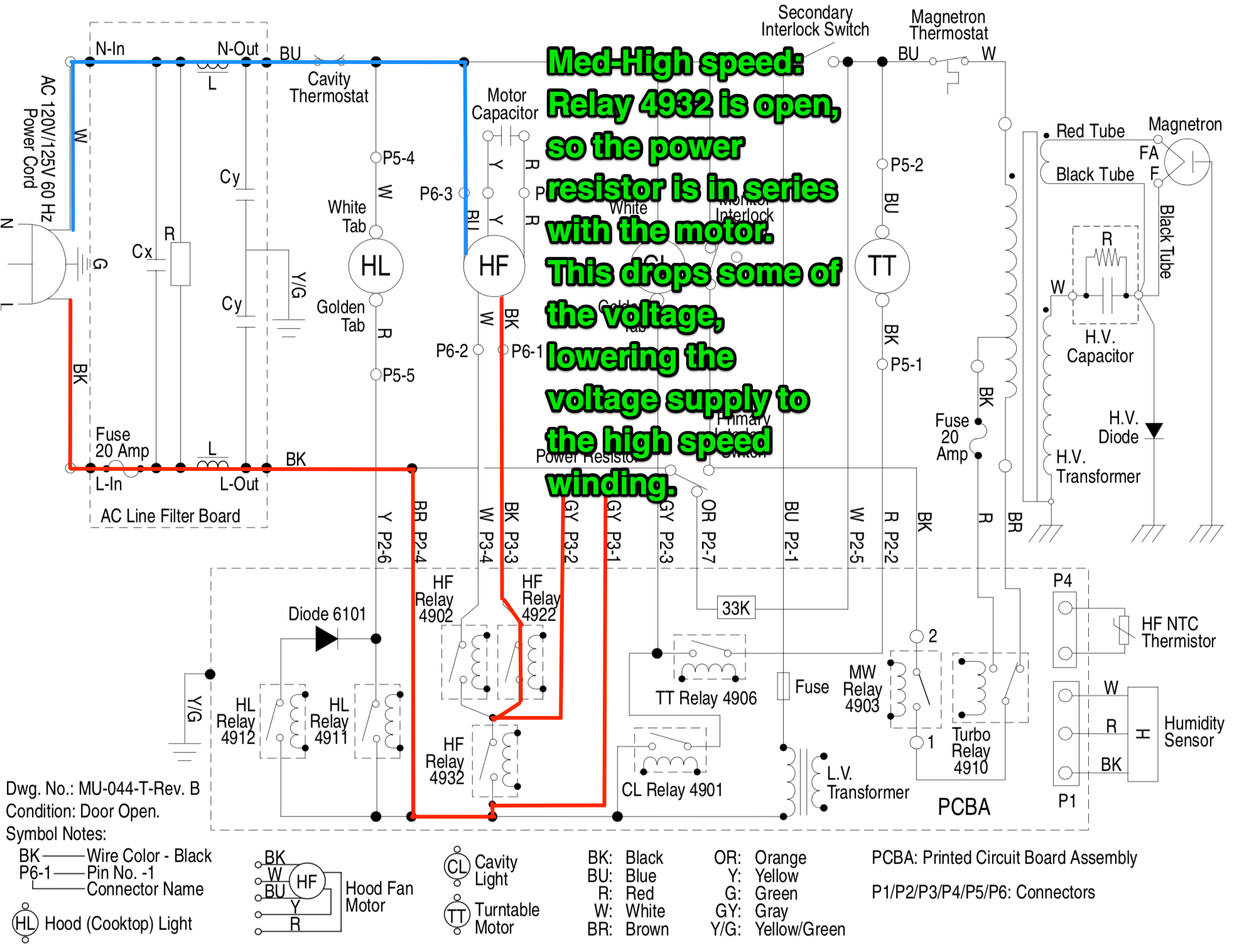
You can figure out the other two speeds for yourself: medium speed would be the low winding with the full voltage supply, and low speed would be the low winding in series with the power resistor.

And that's it: a low-tech way of achieving semi-variable speed in a fan motor. In a higher-end model, you would just have a variable-speed BLDC motor with infinitely variable speed. But I'm sure the engineers who had to shave down the production cost of these microwaves are proud of themselves for coming up with this little configuration.

Want to learn to decipher schematics like a real tech? Click here to check out our Core Appliance Repair Training course over at the Master Samurai Tech Academy.

  • Like 3

11 Comments


Recommended Comments

Looks like the Power Resistor is doing a lot of work on low speed!

  • Like 1
Link to comment

No doubt about it, this is cleaver! Now if we knew how many watts the resistor could take before cooking out we could know the value of the resistor as well? Picking apart the parts and knowing the formulas to derive a repair would be easy for you samurai family but not having seen the formulas in use for such leaves me just educated enough to still know I don’t know it all.

Link to comment
  • Team Samurai
Samurai Appliance Repair Man

Posted

On 2/4/2023 at 3:18 PM, Far field said:

Now if we knew how many watts the resistor could take before cooking out we could know the value of the resistor as well?

Not necessarily. The wattage rating is based on how much heat the resistor can handle. So you can have a 100 ohm resistor rated for 1 watt or a 100 ohm resistor rated for 500 watts. The 500 watt resistor will be much bigger in size than the 1 watt resistor so it can tolerate and dissipate more heat. 

  • Like 1
Link to comment

If the relays 4932 on with individual 4902 speed 1 4922 speed 2 both relays with 4932 speed 3 then with 4932 open and using the resistor  P3-1 + P3-2 with 4902 Speed 4, 4922 speed 5 and with both 4902 & 4922 + P1 & P3 speed 6 so the motor is only 3 speed but can have 6 speeds. The way I see it anyway

Link to comment
  • Team Samurai
Son of Samurai

Posted

14 hours ago, Far field said:

If the relays 4932 on with individual 4902 speed 1 4922 speed 2 both relays with 4932 speed 3 then with 4932 open and using the resistor  P3-1 + P3-2 with 4902 Speed 4, 4922 speed 5 and with both 4902 & 4922 + P1 & P3 speed 6 so the motor is only 3 speed but can have 6 speeds. The way I see it anyway

If I understand your meaning, it sounds like you’re saying that both speed windings could be energized at the same time. But the motor wouldn’t run properly in that state. So the control would never be programmed to close relays 4902 and 4922 at the same time.

Link to comment

I tried to post this earlier. From the logic it seems I see no way of knowing how the relays cannot maker together at the same time thus adding in 2 more speeds. Reason is as you stated the specks on the sheet are erroneous and as such may not include all information. Unless the motor type by observance can determine only 2 speeds or some information is being withheld about the relays on the board I conclude my hypothesis is possible. If the readings are erroneous on the chart then how do you proclaim that it is complete? I would say it’s a crap shoot. Unless stated on a switch or device not shown in the diagram.  

Link to comment
  • Team Samurai
Son of Samurai

Posted

3 hours ago, Far field said:

I tried to post this earlier. From the logic it seems I see no way of knowing how the relays cannot maker together at the same time thus adding in 2 more speeds. Reason is as you stated the specks on the sheet are erroneous and as such may not include all information. Unless the motor type by observance can determine only 2 speeds or some information is being withheld about the relays on the board I conclude my hypothesis is possible. If the readings are erroneous on the chart then how do you proclaim that it is complete? I would say it’s a crap shoot. Unless stated on a switch or device not shown in the diagram.  

You're correct that my statement about the speed windings isn't a conclusion you can come to just from looking at the schematic. But it's not a guess, either -- it's the only logical conclusion based on knowledge of how this technology works.

This is a PSC motor with two different speed windings. Each of those speed windings is physically wound such that it creates a magnetic field which will drive the motor to spin at a certain speed. No motor with speed windings is designed to run with both of those windings energized at the same time. The motor would draw excessive amps, and it probably would not even start.

That's why I said that the control would never be programmed to close both relays at the same time. It would produce a state that's wholly undesirable and nonfunctional, and therefore can't be the intended.

This is a situation where you have to bring knowledge about the technology you're discussing to bear, which is part of what we do as techs. Just looking at the schematic in isolation isn't enough.

  • Like 2
Link to comment
  • Team Samurai
Samurai Appliance Repair Man

Posted

4 hours ago, Far field said:

From the logic it seems I see no way of knowing how the relays cannot maker together at the same time thus adding in 2 more speeds.

Well, there’s logic based on incorrect assumptions or incorrect data and then there’s physics based on the real world.

Are you saying that two speed windings on a multispeed single phase motor could be energized at the same time to produce two additional speeds? I'll tell you that a multispeed, single phase motor will not run this way. That’s not my opinion or hypothesis, that’s physics. Try it out in your shop and let us know how it goes. 

So even though some of the reported voltage drops in the table are incorrect, this does not change the reality (physics) that  you can't energize two speed windings at the same time in a single phase motor with multiple speed windings and expect to run. That's a condition imposed by the physics of how electric motors work. 


  • Like 1
Link to comment
12 hours ago, Son of Samurai said:

You're correct that my statement about the speed windings isn't a conclusion you can come to just from looking at the schematic. But it's not a guess, either -- it's the only logical conclusion based on knowledge of how this technology works.

This is a PSC motor with two different speed windings. Each of those speed windings is physically wound such that it creates a magnetic field which will drive the motor to spin at a certain speed. No motor with speed windings is designed to run with both of those windings energized at the same time. The motor would draw excessive amps, and it probably would not even start.

That's why I said that the control would never be programmed to close both relays at the same time. It would produce a state that's wholly undesirable and nonfunctional, and therefore can't be the intended.

This is a situation where you have to bring knowledge about the technology you're discussing to bear, which is part of what we do as techs. Just looking at the schematic in isolation isn't enough.

Very well explained. And I was thinking that a blower on a fan motor in HVAC had 2 windings making 3 speeds but I remember now that only 1 is used at a time. The other is locked out while desired speed is engaged. My bad. 

  • Like 1
Link to comment
razor ramon

Posted

HI  

can you please help me figur out the capacitore configuration with the coils ?

as i already know run cap is supposed to be connected in series with both windings main and run and if i ought to measure 80ohms across BU-R  so i surmise that R is connected to the auxilary winding  and since we have 2 run windings here so is Y connected to to both main windings(high and low)?


Link to comment
  • Team Samurai
Son of Samurai

Posted

2 hours ago, razor ramon said:

HI  

can you please help me figur out the capacitore configuration with the coils ?

as i already know run cap is supposed to be connected in series with both windings main and run and if i ought to measure 80ohms across BU-R  so i surmise that R is connected to the auxilary winding  and since we have 2 run windings here so is Y connected to to both main windings(high and low)?


We have a webinar recording all about PSC motors which should give you a very thorough understanding of how they work. It's covering them in a different application (as a washer drive motor), but the fundamental principles of the technology are the same.


Link to comment
×
×
  • Create New...