FAQs | Repair Videos | Academy | Newsletter | Contact
Search the Community
Showing results for tags 'double oven'.
-

Jenn-Air Freestanding Double Oven Dual Fuel Range Service Manual
Samurai Appliance Repair Man posted a file in Appliance Repair Manual Pot Luck Supper
-
New Appliance Service Manual added: Jenn-Air Freestanding Double Oven Dual Fuel Range Service Manual
Samurai Appliance Repair Man posted a topic in Appliance Service Manual Requests Forum
File Name: Jenn-Air Freestanding Double Oven Dual Fuel Range Service Manual File Submitter: Samurai Appliance Repair Man File Submitted: 23 Nov 2013 File Category: Appliance Repair Manual Pot Luck Supper Jenn-Air Freestanding Double Oven Dual Fuel Range Service Manual Models JDR8895 JDR8895 Pub 16023417 Click here to download this file -
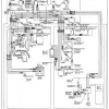
 File Name: Whirlpool Double Oven Techsheet model RBD305PDS14 File Submitter: kdog File Submitted: 16 Nov 2012 File Category: Appliance Repair Manual Pot Luck Supper Specific Model Techsheet Whirlpool Electric Built In Double Wall Oven Model RBD305PDS14 PART NO. 8302068 French and English Francais au Enlais Click here to download this file
-
- 1
-
.png)
-
- Whirlpool
- double oven
- (and 8 more)
-
File Name: Maytag Gemini Double Oven Gas Range Service Manual File Submitter: kdog File Submitted: 14 Nov 2012 File Category: Appliance Repair Manual Pot Luck Supper Models: MGR6772BDB MGR6772BDQ MGR6772BDS MGR6772BDW Freestanding GeminiTM Gas Range PUB 16021694 Click here to download this file
-
File Name: KitchenAid Double Wall Oven Electric File Submitter: kdog File Submitted: 28 Apr 2012 File Category: Appliance Repair Manual Pot Luck Supper KitchenAid Electric Built In Double Wall Oven Job Aid SPECIFICATIONS .................................................................................................................. 1-1 INSTALLATION HIGHLIGHTS................................................................................................ 2-1 Electrical Supply Requirements ......................................................................................... 2-1 Removing & Reinstalling The Oven Door .......................................................................... 2-3 PRODUCT OPERATION ........................................................................................................ 3-1 Air Flow .............................................................................................................................. 3-1 The Oven Shutdown Thermal Fuse & Control Panel Thermal Fuse ................................. 3-2 The Oven Door Latch Assembly ........................................................................................ 3-3 How The Self-Clean Cycle Works ..................................................................................... 3-4 COMPONENT ACCESS ......................................................................................................... 4-1 Component Locations ........................................................................................................ 4-1 Removing The Thermal Fuse, The Oven Control/Display Boards, And The Touch Panel Assembly .................................................................................... 4-2 Removing The Power Supply Wiring Terminal Block And The Upper & Lower Blower Motors ......................................................................... 4-4 Removing The Upper & Lower Oven Door Latch Assembly.............................................. 4-6 Removing An Oven Light & An Oven Temperature Sensor .............................................. 4-8 Removing A Broil Element ................................................................................................. 4-9 Removing A Bake Element .............................................................................................. 4-10 Removing An Oven Shutdown Thermal Fuse ................................................................. 4-11 Removing The Convection Fan Motor Assembly ............................................................ 4-12 Removing The Oven Door Glass, Hinges, & Handle ....................................................... 4-14 Removing The Oven Door Gasket................................................................................... 4-16 COMPONENT TESTING ........................................................................................................ 5-1 Blower Motors .................................................................................................................... 5-1 Oven Temperature Sensor ................................................................................................ 5-1 Convection Fan Motor ....................................................................................................... 5-2 Oven Shutdown Thermal Fuse .......................................................................................... 5-2 Broil Element ..................................................................................................................... 5-3 Bake Element .................................................................................................................... 5-3 Oven Door Latch Assembly ............................................................................................... 5-4 Control Panel Thermal Fuse .............................................................................................. 5-4 DIAGNOSIS & TROUBLESHOOTING.................................................................................... 6-1 Diagnostics ........................................................................................................................ 6-1 Fahrenheit To Celsius Conversion .................................................................................... 6-1 Programming The Cavity Size ........................................................................................... 6-1 Electrostatic Discharge Sensitive Electronics .................................................................... 6-1 Failure/Error Display Codes—Tech Sheets 4451887C & 4451888A ................................ 6-2 Failure/Error Display Codes—Tech Sheet 4452022A ....................................................... 6-3 Relay Logic Chart—Tech Sheets 4451887C & 4451888A ................................................ 6-4 Relay Logic Chart—Tech Sheet 4452022A ....................................................................... 6-4 Control Panel Test Locations—Tech Sheets 4451887C & 4451888A .............................. 6-5 Control Panel Test Locations—Tech Sheet 4452022A ..................................................... 6-6 - iv - WIRING DIAGRAMS & STRIP CIRCUITS.............................................................................. 7-1 Schematic Diagram 1 (Tech Sheet 4451887C) ................................................................. 7-1 Strip Circuits ...................................................................................................................... 7-2 Schematic Diagram 2 (Tech Sheet 4451888A) ................................................................. 7-4 Strip Circuits ...................................................................................................................... 7-5 Schematic Diagram 3 (Tech Sheet 4452022A) ................................................................. 7-7 Strip Circuits ...................................................................................................................... 7-8 Tech Sheet / Model Number Usage Charts ..................................................................... 7-10 Click here to download this file
-
- 1
-
-
- KitchenAid
- wall oven
- (and 6 more)
-
KitchenAid KitchenAid Double Wall Oven Electric
kdog posted a file in Appliance Repair Manual Pot Luck Supper
Version PDF - Job Aid
85 downloads
KitchenAid Electric Built In Double Wall Oven Job Aid SPECIFICATIONS .................................................................................................................. 1-1 INSTALLATION HIGHLIGHTS................................................................................................ 2-1 Electrical Supply Requirements ......................................................................................... 2-1 Removing & Reinstalling The Oven Door .......................................................................... 2-3 PRODUCT OPERATION ........................................................................................................ 3-1 Air Flow .............................................................................................................................. 3-1 The Oven Shutdown Thermal Fuse & Control Panel Thermal Fuse ................................. 3-2 The Oven Door Latch Assembly ........................................................................................ 3-3 How The Self-Clean Cycle Works ..................................................................................... 3-4 COMPONENT ACCESS ......................................................................................................... 4-1 Component Locations ........................................................................................................ 4-1 Removing The Thermal Fuse, The Oven Control/Display Boards, And The Touch Panel Assembly .................................................................................... 4-2 Removing The Power Supply Wiring Terminal Block And The Upper & Lower Blower Motors ......................................................................... 4-4 Removing The Upper & Lower Oven Door Latch Assembly.............................................. 4-6 Removing An Oven Light & An Oven Temperature Sensor .............................................. 4-8 Removing A Broil Element ................................................................................................. 4-9 Removing A Bake Element .............................................................................................. 4-10 Removing An Oven Shutdown Thermal Fuse ................................................................. 4-11 Removing The Convection Fan Motor Assembly ............................................................ 4-12 Removing The Oven Door Glass, Hinges, & Handle ....................................................... 4-14 Removing The Oven Door Gasket................................................................................... 4-16 COMPONENT TESTING ........................................................................................................ 5-1 Blower Motors .................................................................................................................... 5-1 Oven Temperature Sensor ................................................................................................ 5-1 Convection Fan Motor ....................................................................................................... 5-2 Oven Shutdown Thermal Fuse .......................................................................................... 5-2 Broil Element ..................................................................................................................... 5-3 Bake Element .................................................................................................................... 5-3 Oven Door Latch Assembly ............................................................................................... 5-4 Control Panel Thermal Fuse .............................................................................................. 5-4 DIAGNOSIS & TROUBLESHOOTING.................................................................................... 6-1 Diagnostics ........................................................................................................................ 6-1 Fahrenheit To Celsius Conversion .................................................................................... 6-1 Programming The Cavity Size ........................................................................................... 6-1 Electrostatic Discharge Sensitive Electronics .................................................................... 6-1 Failure/Error Display Codes—Tech Sheets 4451887C & 4451888A ................................ 6-2 Failure/Error Display Codes—Tech Sheet 4452022A ....................................................... 6-3 Relay Logic Chart—Tech Sheets 4451887C & 4451888A ................................................ 6-4 Relay Logic Chart—Tech Sheet 4452022A ....................................................................... 6-4 Control Panel Test Locations—Tech Sheets 4451887C & 4451888A .............................. 6-5 Control Panel Test Locations—Tech Sheet 4452022A ..................................................... 6-6 - iv - WIRING DIAGRAMS & STRIP CIRCUITS.............................................................................. 7-1 Schematic Diagram 1 (Tech Sheet 4451887C) ................................................................. 7-1 Strip Circuits ...................................................................................................................... 7-2 Schematic Diagram 2 (Tech Sheet 4451888A) ................................................................. 7-4 Strip Circuits ...................................................................................................................... 7-5 Schematic Diagram 3 (Tech Sheet 4452022A) ................................................................. 7-7 Strip Circuits ...................................................................................................................... 7-8 Tech Sheet / Model Number Usage Charts ..................................................................... 7-10 -
File Name: Kitchenaid Double Wall Oven Kebc208kwh02 File Submitter: kdog File Submitted: 28 Apr 2012 File Category: Appliance Repair Manual Pot Luck Supper Techsheet for Model Kebc208kwh02 KitchenAid Built-In Double Wall Oven Click here to download this file
-
KitchenAid Kitchenaid Double Wall Oven Kebc208kwh02
kdog posted a file in Appliance Repair Manual Pot Luck Supper
-
Hello hello. I have recently encountered this beast of an oven and was hoping I could dig up a service manual for it. Jenn Air tech info is hard for me to get. So if any of you can point me in the right direction, that would be great Thanks!
-
Bosch HBL-HBN 5000 Series Oven Model Configuration, Test Procedure, & Error Codes
Samurai Appliance Repair Man posted a file in Appliance Repair Manual Pot Luck Supper
-
New Appliance Service Manual added: Bosch HBL-HBN 5000 Series Oven Model Configuration, Test Procedure, & Error Codes
Samurai Appliance Repair Man posted a topic in Appliance Service Manual Requests Forum
File Name: Bosch HBL-HBN 5000 Series Oven Model Configuration, Test Procedure, & Error Codes File Submitter: Samurai Appliance Repair Man File Submitted: 10 Apr 2012 File Updated: 10 Apr 2012 File Category: Appliance Repair Manual Pot Luck Supper Bosch HBL-HBN 5000 Series Oven Model Configuration, Test Procedure, & Error Codes Click here to download this file -
File Name: Maytag Gemini MER6770 Electric Range Service Manual File Submitter: kdog File Submitted: 11 Mar 2012 File Category: Appliance Repair Manual Pot Luck Supper Service Manual for Maytag Gemini Electric Range MODELS COVERED IN THIS MANUAL: MER6770AAW MER6770AAB MER6770AAC PUB 16010107 Click here to download this file