
Can You Identify This Sensing Line and These Useful EEPs?

Entry posted by Son of Samurai in Tech Talk
1,817 views
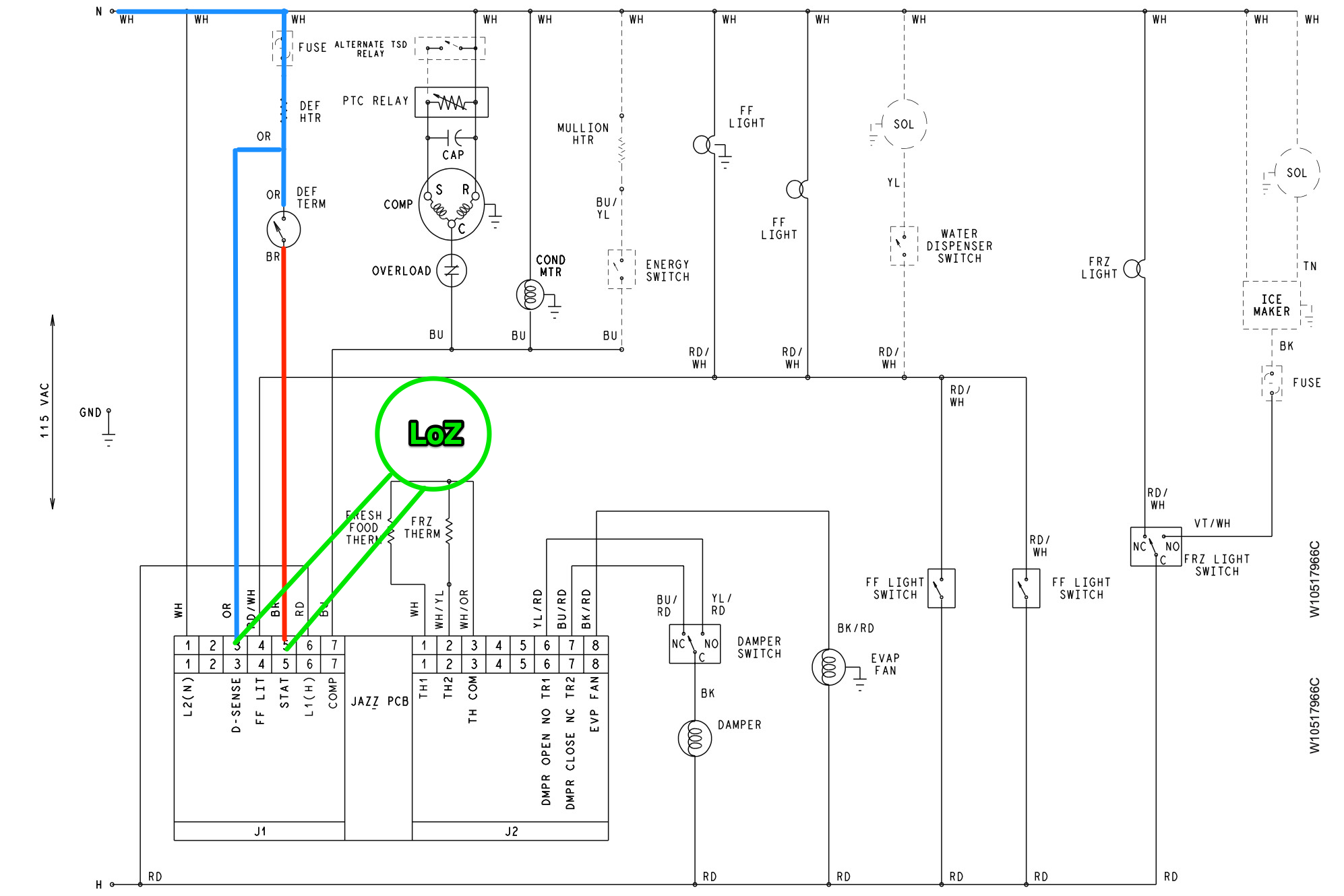
Take a look at the defrost circuit on this Whirlpool refrigerator:
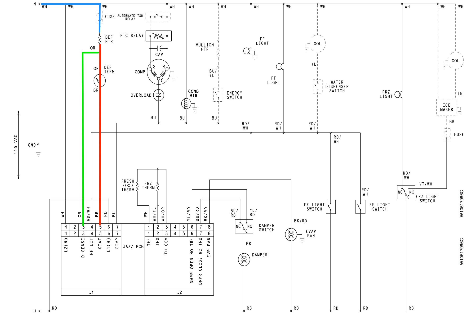
Looks pretty standard -- there's just a defrost heater and a defrost terminator in the circuit, and voltage is supplied to the circuit by the control board.
But what is the purpose of the wire marked in green that tags off to J1-3?
If you look closely, you'll see that that pin on the control is labeled D-SENSE -- so that's a sensing line. This means that the purpose of that wire is to give the control board information about a circuit. In this particular case, it lets the control board sense the state of the defrost terminator.
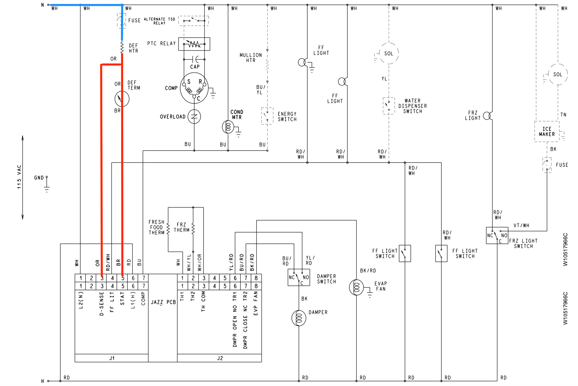
How does that actually work? Well, if the defrost terminator is closed, Line voltage will be present at J1-3, like so:
But when the terminator is open, Neutral is instead present at J1-3, like so:
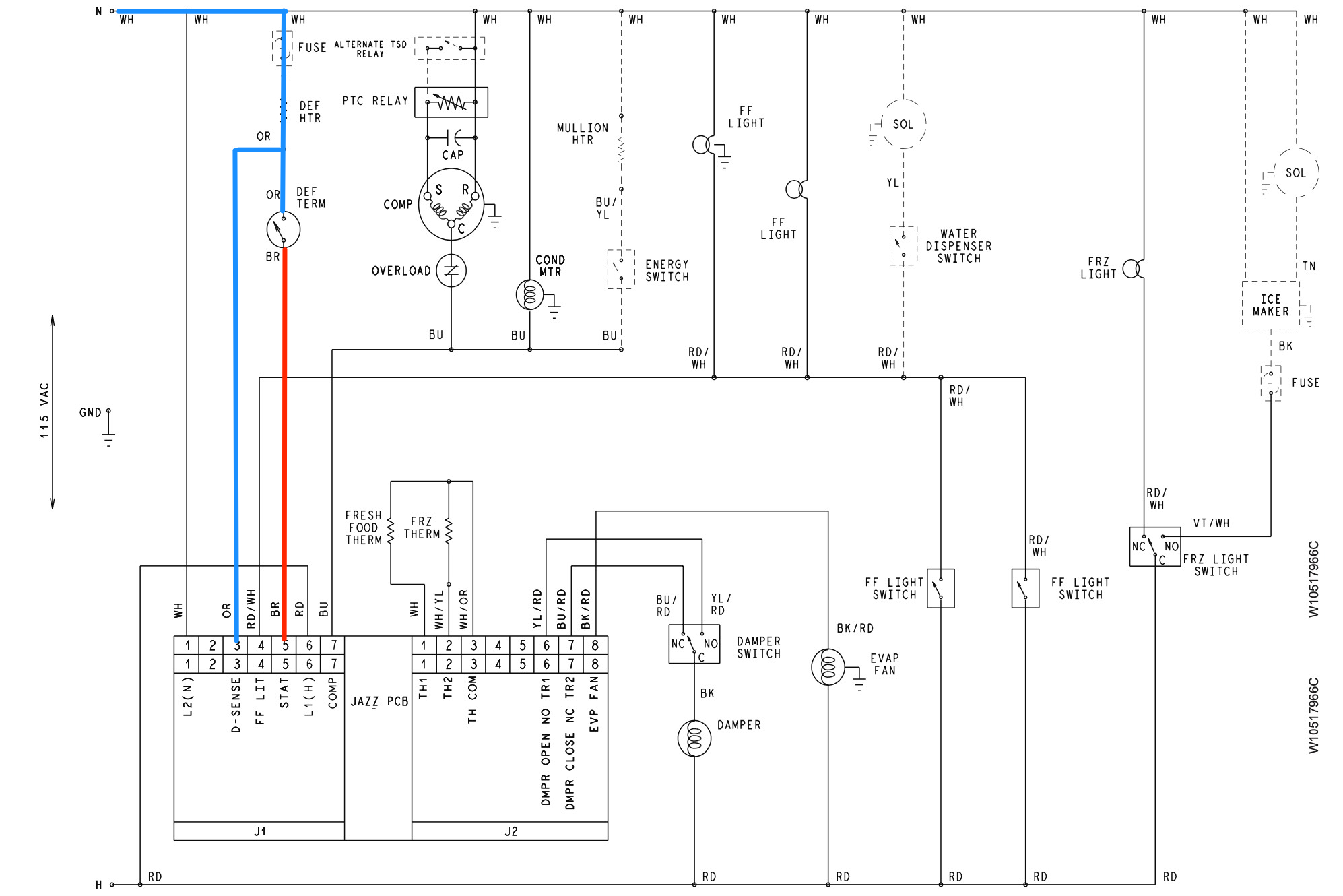
This is how the control board's adaptive defrost algorithm gets the info it needs -- based on how long Line is present or absent at J1-3, the control is programmed to adjust the length of defrost cycles.
It's useful for our troubleshooting purposes to know how the control board thinks, but the presence of this sensing line is also useful for our own troubleshooting purposes. Because the sensing line is there, we are able to perform an electrical measurement on the defrost terminator without disassembling to reach the defrost circuit.
Having put the unit into forced defrost, we can perform a measurement with our loading voltmeter like so:
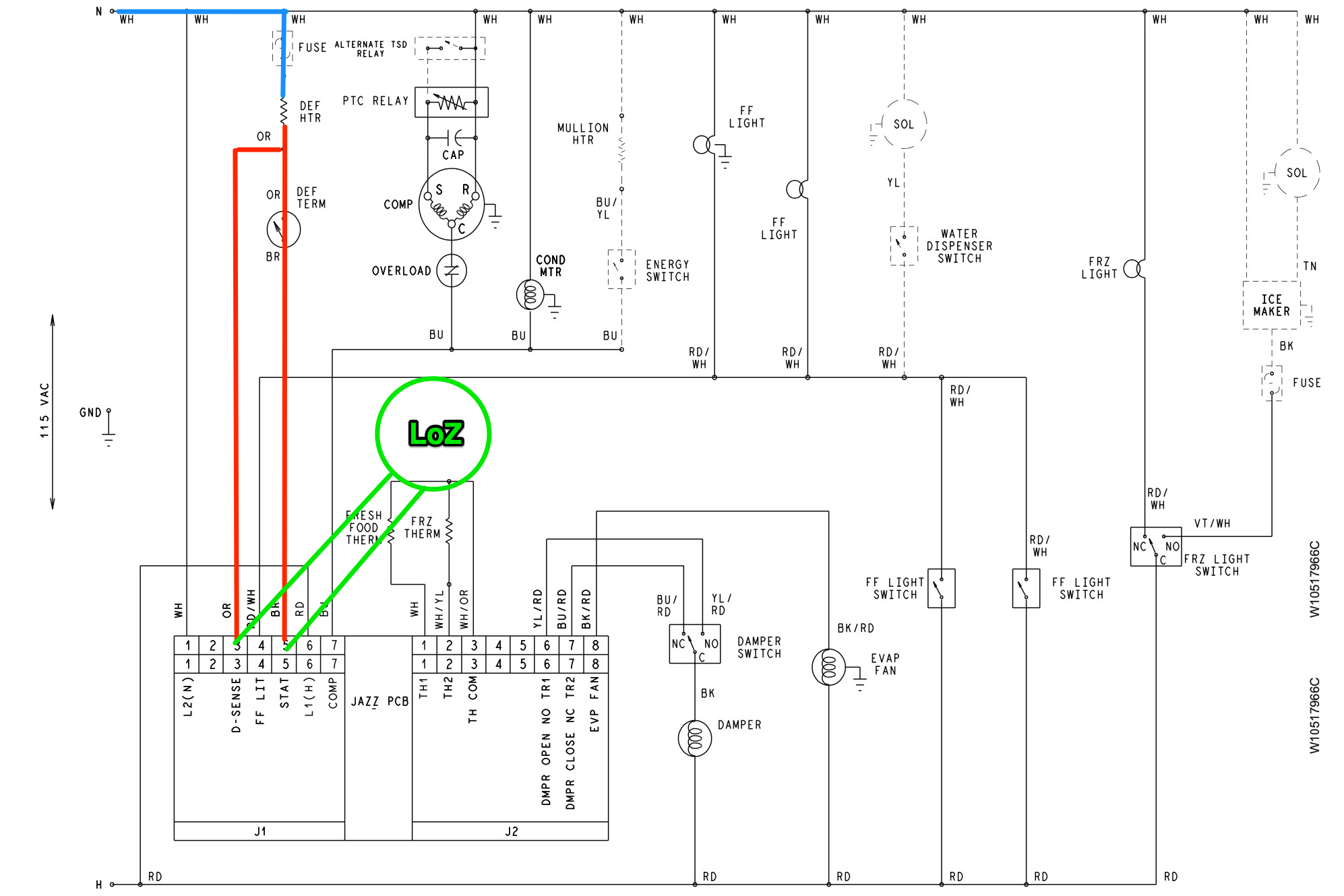
If the defrost terminator is closed, as shown, then we would read 0 VAC on our meter, since we're reading from Line to Line.
If the terminator were open, like so...
...then we would read 120 VAC, since we're now reading from Line to Neutral.
There's even more that this sensing line lets us do right from the control board. Because the line splits the defrost circuit in half, we can use it to check if that heater has gone open with another voltage measurement.
This time, we won't place the unit in forced defrost. Instead, we're going to use the control board's line supply as a reference to check for the presence of a good Neutral at J1-3, like so:
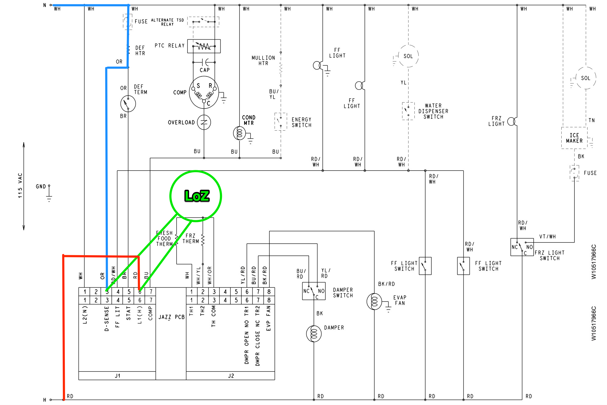
Because we're using a loading meter, we will only read voltage between these two points if the heater has continuity. If you get 0 VAC, then you know you have an open heater.
All of these clever tests are not just so we can feel smart -- it actually saves time (and therefore money) on the job. The less disassembly you have to do, the more jobs you can get done and the less liability you have to take on. Work smarter, not harder!
Want to get in on the action? Join the Brotherhood of Techs at Appliantology.
- Appliantology.org is a cultivated, private community of techs.
- Get solid tech advice from working, professional techs and business owners.
- Avoid the endless noise and guesswork thrown at you from groups on social media.
- Download the service manuals, tech sheets, and service bulletins you need to git 'er done.
Join the Brethren in the Craft right now with our membership options at Appliantology and see how it can help you in your business starting today.
-
.png) 12
12
3 Comments
Recommended Comments