How to properly replace the thermistors in a refrigerator: an illustrated and annotated guide
A special treat today, kids: Sublime Master Bob-tech is featured in this week's edition of Techniques from the Masters™ for replacing the thermistors in a GE refrigerator. The technique demonstrated here is on a GE bottom-mount refrigerator but the same technique applies to all brands and types of refrigerators that use thermistors for temperature sensing. The idea is that you want those connections to have as little resistance as possible, ideally less than 1/2 ohm. Samsung, for example, prefers soldered connections but GE also says that using crimp connectors with silicon applied in the open end is okay, too.
The reason that low-resistance connections are desirable is to eliminate inaccuracies in temperature measurements. The thermistor itself is really just a negative temperature coefficient (NTC) resistor (read more here) whose resistance changes with temperature and is read by the control board. So any resistance introduced into the circuit will just result in less accurate temperature sensing by the board. In this case, higher resistance is interpreted by the board as lower temperature. If the additional resistance is high enough, this will result in a warm compartment because the board will interpret that higher resistance as colder temperatures and will not call for the compressor to come on enough to cool the compartment.
By following these Techniques from the Masters™, you'll help assure that you're making a good repair that will not introduce other problems.
You can buy the replacement thermistors with a 365-day return policy here ==> http://www.repairclinic.com/PartDetail/Thermistor/WR55X10025/914093?RCAID=24038
Here are Sublime Master Bob-tech's field notes on this technique
I finally got around to changing my thermistors.
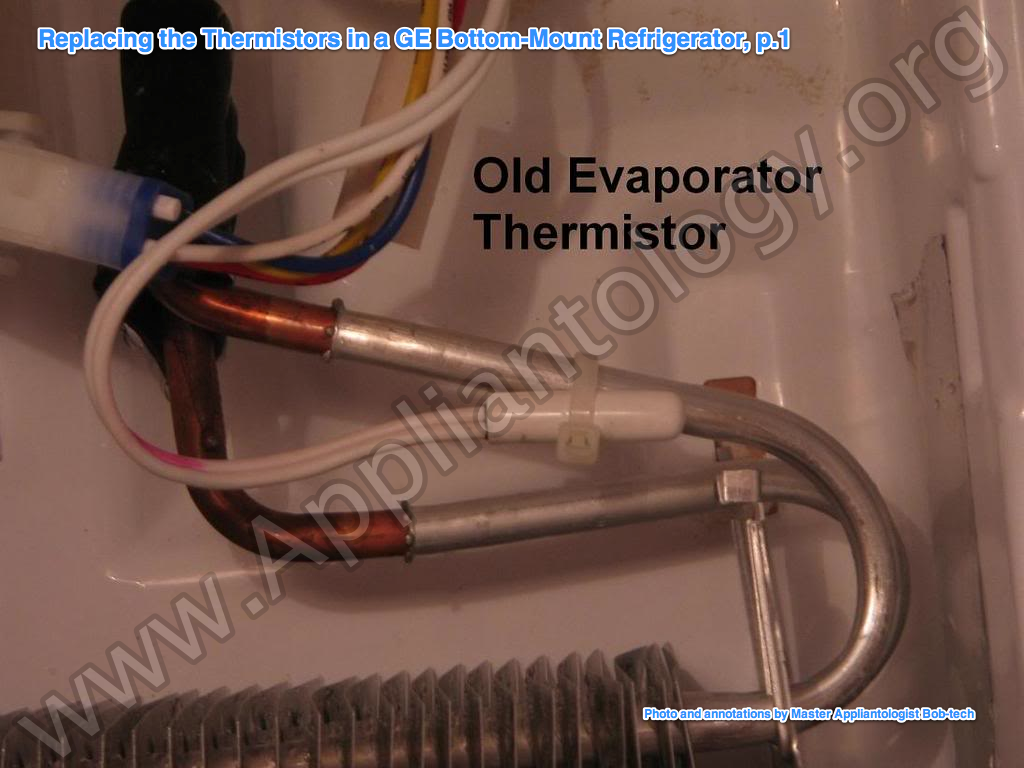
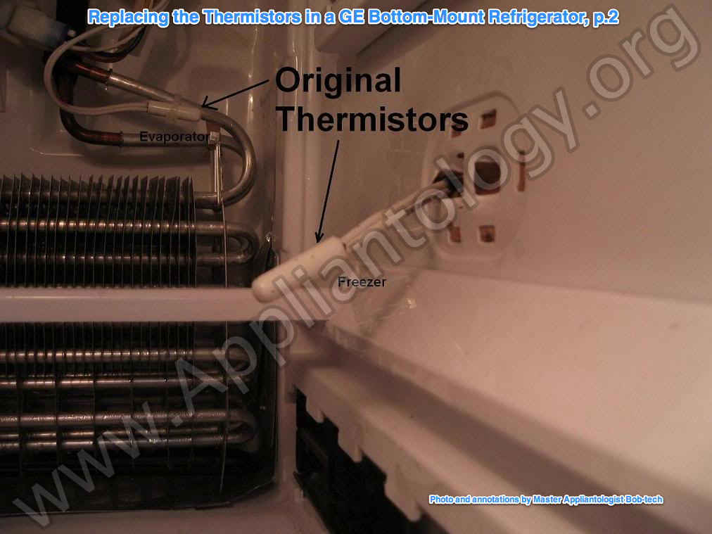
1. On the evaporator, tie wrapped to the coil.
2. One in the freezer, right side wall.
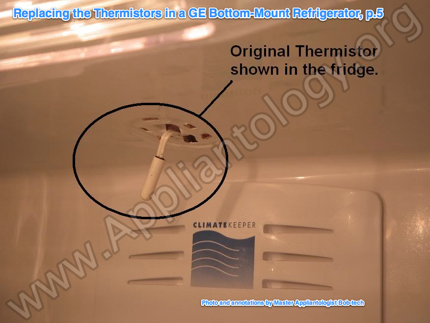
3. One in the fridge, Ceiling, back-center.
The evaporator thermistor requires the most work to get to, but it's the easiest to work with. The one in the freezer and fridge don't have much wire room to work with.
This job is a little time consuming, but it's fairly easy. All you are doing is getting to the thermistors, cutting out the old and puting in the new.
Note: Thermistors are not polarized....so you can't hook them up backwards.
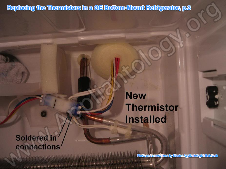
I strongly recomend soldering in your new thermistors.
I also recomend using heatshrink. Don't use black tape.
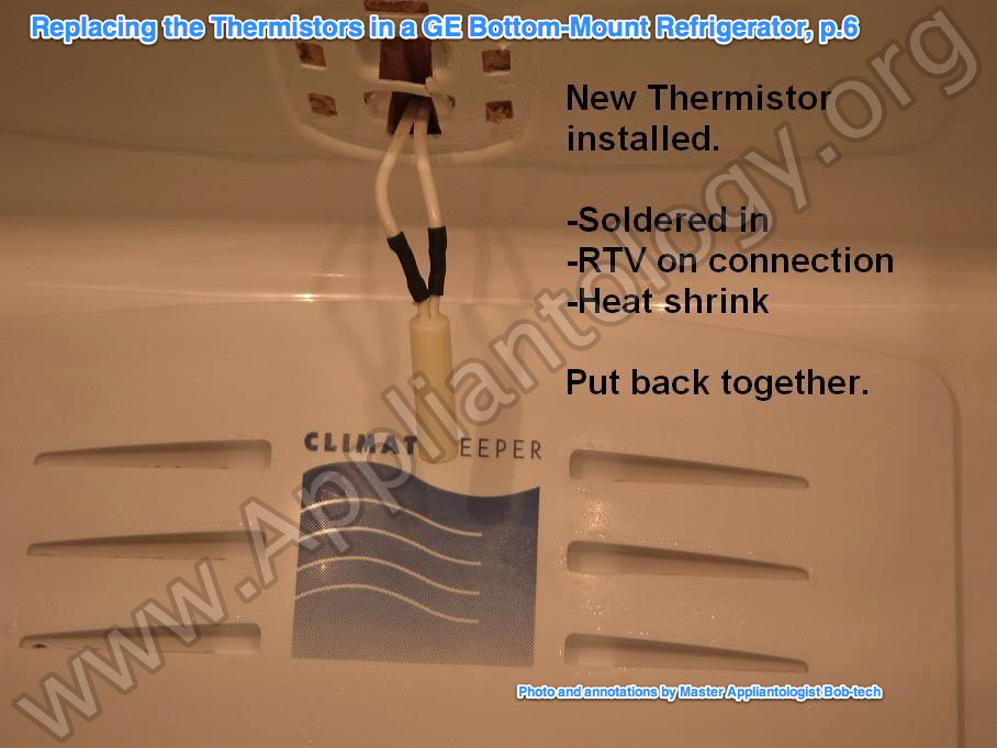
For each of my thermistors, I soldered each connection, then I covered the solder joints in RTV. Then I covered each connection with heatshrink. If you go the route of changing these thermistors, you must make a solid connection, and you must secure it. If you don't, then over time the connection will corroid and cause the main board to read incorrect values.
The connetctions for the freezer and fridge thermistor are tight because very little wire length is given to you. I see in the GE technical pdf they use marrets for this service. All I can say is....... good luck. Those marrets better be tiny. Besides... I would never use marrets in a situation like this.
When soldering in the thermistors, make sure the fridge is not plugged in.
Most soldering iron tips are earth grounded!
I also recomend that you test your new thermistors before installing them.
You can do this by placing them in a large glass filled with as much ice and water as possible. This will ensure the closest temperature reference at 0oC/32F.
Let the thermistors sit in the ice water for a good 5-10minutes.
Ensure they are well seated amongst the ice and water.
Then measure the resistance of each thermistor while they are sitting in the ice water.
You should be reading in the range of 14K-15Kohm.
I'll come back and report the status of my fridge when it's been enough of a testing period.
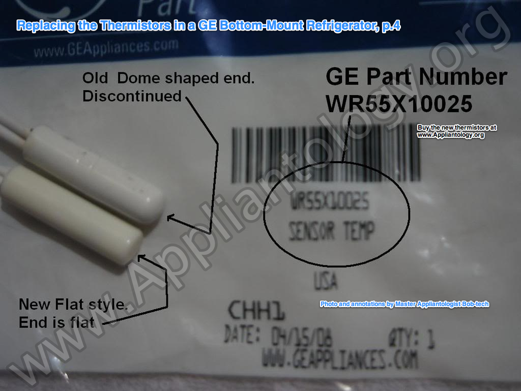
I took a picture of an old and new thermistor to show the difference in body.
In an earlier post in this thread, Jeff indicated that the bullet or rounded end shaped thermistors were problematic. I had the bullet shaped thermistors, so I changed out for the new flat end style.
Here are the pics....
Source ==> http://appliantology...ss/page__st__20
-
.png) 2
2



2 Comments
Recommended Comments