FAQs | Repair Videos | Academy | Newsletter | Contact
Search the Community
Showing results for tags 'triac'.
-

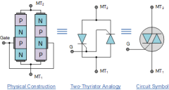
Triac schematic symbol
Samurai Appliance Repair Man posted a gallery image in The Appliantology Gallery
From the album: Triacs
-
From the album: Triacs
-
- triac
- triggering
-
(and 2 more)
Tagged with:
-

Triac PN junction block diagram
Samurai Appliance Repair Man posted a gallery image in The Appliantology Gallery
From the album: Triacs
-

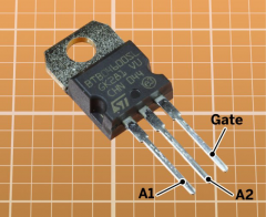
Triac physical package
Samurai Appliance Repair Man posted a gallery image in The Appliantology Gallery
From the album: Triacs
-

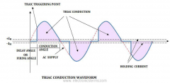
Triac output and gating waveform
Samurai Appliance Repair Man posted a gallery image in The Appliantology Gallery
From the album: Triacs
-

Triac output and gating pulses oscilloscope
Samurai Appliance Repair Man posted a gallery image in The Appliantology Gallery
From the album: Triacs
-
- triac
- oscilloscope
-
(and 2 more)
Tagged with:
-
Need to know... The output of the motor control circuit should only put 120VAC on one winding (CCW or CW) at a time? If I measure the output of the control board I seem to get 120VAC on both windings, at the same time.The start capacitor checks good, so I'm thinking the Triac circuitry may have gone bad. It there a way the triac for the motor control can be replaced, instead of the whole control board? Whenever the motor is supposed to drive (spin, agitate) it just hums. As I said, there is 120VAC on both windings at this time. I would assume during spin, it should only have 120VAC on one winding (CW or CCW).... Have run the diagnostics and it keeps saying replace main control board. Seems there is a less expensive way to repair, $220.00 may be more than it is worth....

.png.f1622b6167220d8c8c781a7c863c9adb.png)


