This Circuit Looks Like It Can Never Run... And Yet It Does
We're so used to our fancy control boards and computer-controlled appliances that we sometimes forget how to troubleshoot old-skool circuits. While these circuits are generally pretty straightforward, the manufacturers employed some clever tricks that can mess with your head if you don't have a firm grasp of simple AC circuits.
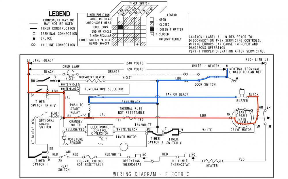
Take the buzzer in this dryer as an example:
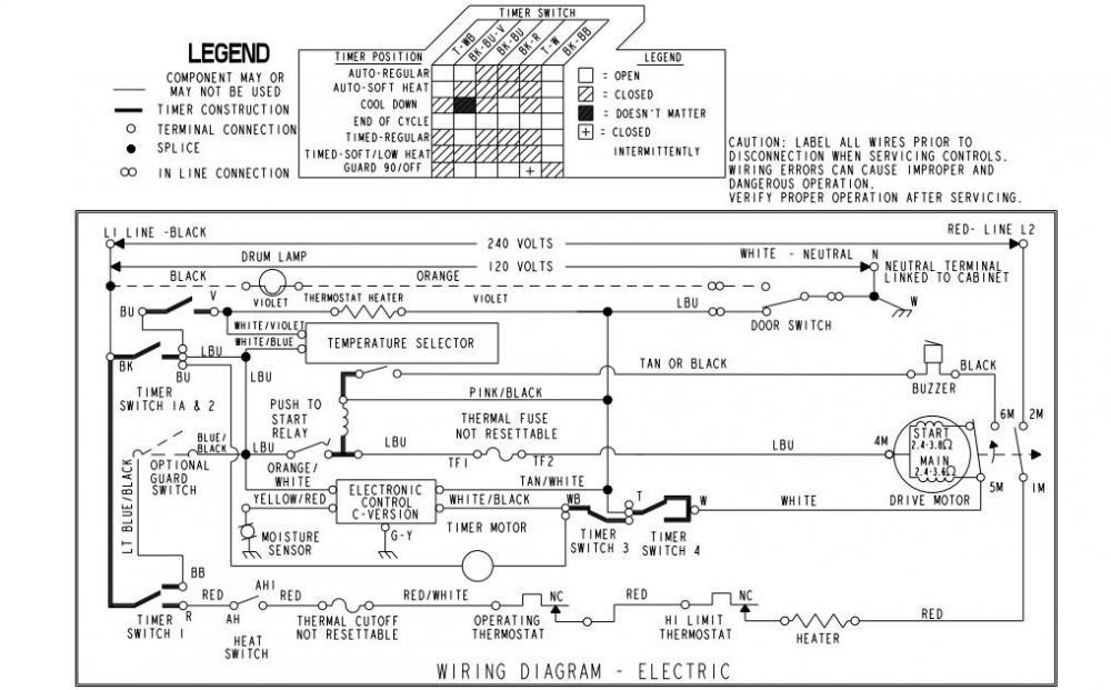
The Tan or Black side of the buzzer goes straight to neutral through that unlabeled switch beneath the temperature selector. What about the other side? Well, with contacts 5M and 6M of the centrifugal switch closed, it goes through contacts T-W...and straight to neutral.
Huh? That's not gonna work. How does this buzzer ever run?
Depending on how good you are with AC circuits, this is when you might start throwing out possible explanations, some more plausible than others. There's a mistake in the schematic? Maybe. The buzzer is powered by back-EMF from the motor? Doubtful. And what's up with that weirdly drawn Timer Switch 4? Looks like it's closed no matter what position it's in...
Before we dive into the actual explanation, here are a few other schematics that are electrically almost identical to this one.
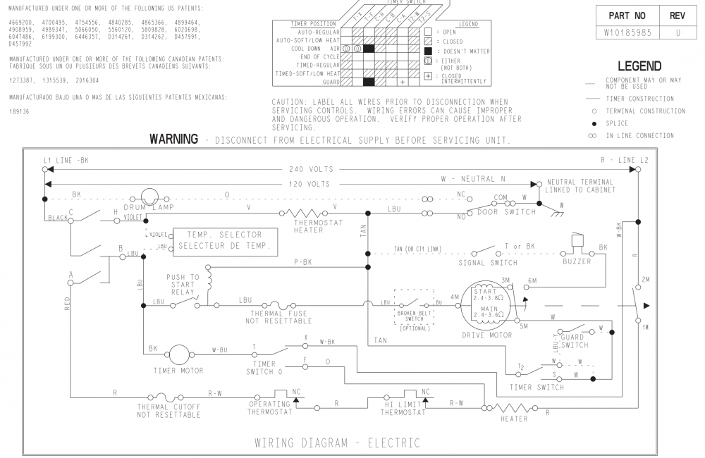
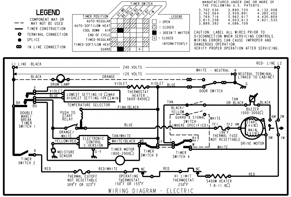
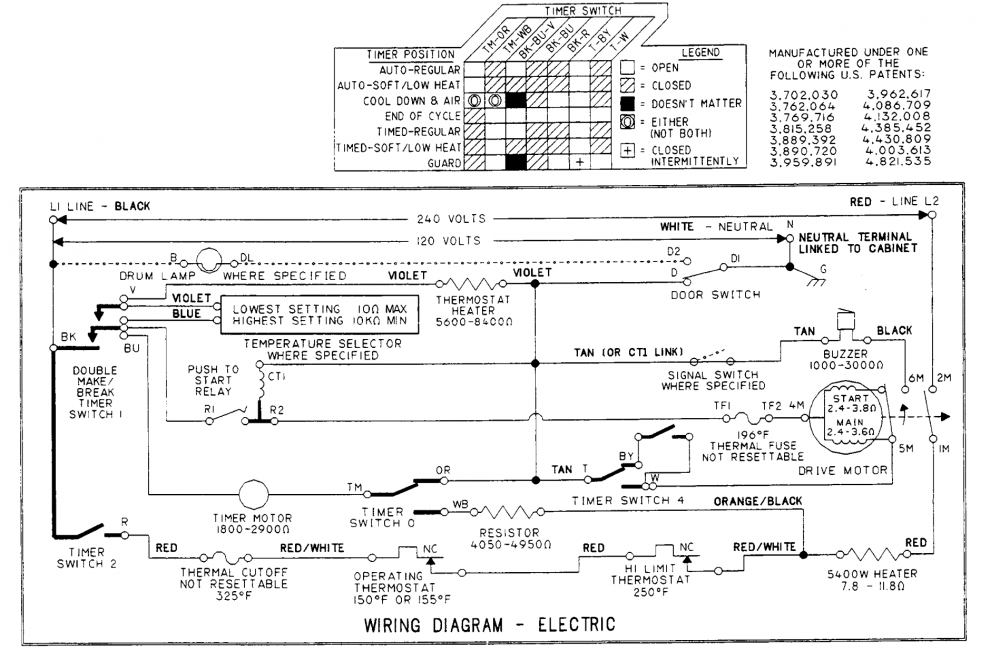
They all have the exact same arrangement for the buzzer circuit, and they all have that funky and useless-looking Timer Switch 4/T-W contacts. There's something going on right under our noses here.
To realize what it is, you have to a) totally grasp simple AC circuits, and b) have a functional understanding of how the motor centrifugal switch works. Let's break it down:
When the dryer has reached the end of the cycle, it opens those T-W contacts. And yes, there is an open position -- that's a three-position switch, with the middle as the open position. Once that switch opens, neutral is cut off from the motor. But the motor doesn't just stop spinning immediately; it has to wind down. While it's slowing down, those centrifugal switch contacts 5M-6M stay closed for a few seconds, until the rotation has slowed enough for them to go open. This is just how centrifugal switches work.
The upshot of all this is that, for a few seconds at the end of the cycle, the buzzer gets Line voltage through the centrifugal switch. As simple as that. A trace of the circuit is shown below.
You'll notice that the buzzer is a load in series with the main winding of the motor. Does this mean that the main winding is kept active, never allowing the motor to stop? Obviously not. The buzzer's resistance is much higher than the winding's measly 3 ohms, meaning that it drops the lion's share of the voltage. The winding acts more or less as a wire.
Don't believe me? Believe Whirlpool, then -- they made the dryer, after all. Check out page 21 of document #3 in this link:
This is one of many examples of the tricky things that manufacturers did back in the day when they couldn't rely on programmed microchips to get things done. While it may seem like a simple old circuit (and it is, really), you've still got to stay on your toes and not get cocky when approaching these antiquated schematics.
-
.png) 6
6
-
 1
1

.png.f1622b6167220d8c8c781a7c863c9adb.png)

3 Comments
Recommended Comments