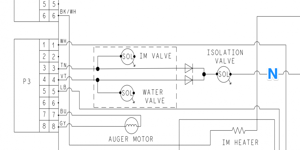
How would you test these water valves?
How would you go about troubleshooting the valves?
As always, we should start with a load analysis on your load (or in this case, loads) of interest. That means identifying how each valve gets line and neutral. (The wire marked with a blue N connects directly to neutral).
You should immediately see that something is off. How do the IM and water valves get neutral?
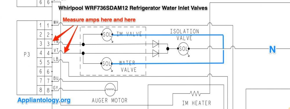
The answer is that someone over at Whirlpool made a whoopsie when drawing this schematic. There should be a line coming out of each of those valves, connecting to somewhere on the right side of the isolation valve. This would put the the IM valve in parallel with with isolation valve, and the water valve also in parallel with the isolation valve. Note that the IM and water valves are not, however, in parallel with each other.
Next: What would be the most informative and reliable measurement(s) to make?
As is often the case in AC circuits, the reading that will most reliably tell you what's going on in this circuit would be amperage. Amperage is a reliable test because a) you do the test while the circuit is energized, so you don't get fooled by components failing under load, and b) it serves as a good proxy for watts, and AC loads are all about watts. But none of us carry wattmeters around, so amps do just fine.
You can use a clamp-on amp meter to check all three valves: isolation, ice maker, and water. Check out this markup:
Notice the blue lines drawn on the markup above? Those are the missing Neutrals for the IM and Water valves that the Whirlpool draftsman forgot to draw in.
As you can see, the ice maker and water valves are both in parallel with the isolation valve. So we're dealing with two pairs of parallel circuits. This means that when you put your amp clamp on P3-3, you're measuring the current through both the isolation valve and the ice maker valve. Similarly, on P3-4, you're measuring the current through the water valve and the isolation valve.
The tech sheet gives a wattage spec for all three valves. The isolation valve is 20 watts, the water valve is 20 watts, and the ice maker valve is 35 watts. Using a simple Ohm's law equation, I = P/E, you can calculate the expected amperage of each valve, then add the values together depending on which wire you're measuring.
When you're doing the calculation, you want to be sure to account for the diodes in the power supply for the Isolation valve. These diodes cut the voltage supply to the Isolation valve in half because they open every half cycle of the sine wave. So you need to run that equation with 120 VAC for the Water and IM valves but only 60 VAC for the Isolation valve.
Once you crunch those numbers, you find the following expected amperages:
Isolation valve: 0.33 amps
IM valve: 0.29 amps
Water valve: 0.17 amps
Based on those calculations, you know that your amp clamp on P3-3 (the ice maker valve), you should measure about 0.62 amps. At P3-4 (the water valve), you should measure about 0.5 amps.
If your amperage measurements are significantly off of those specs, then you know you've identified an issue in that circuit. But if it's in spec, you can definitively conclude that those valves are in-spec electrically, and you can proceed with your troubleshooting from there. Since solenoid valves are electromechanical devices, you still need to rule out that the valve is in-spec mechanically.
As you can see, amp measurements are an extremely powerful diagnostic tool, and one that more techs need to start using. With a little basic math, you can get a lot of precision in your troubleshooting.
Not sure how to use schematics, electricity, and Ohm's law in your troubleshooting? Want to step your repair game up to the next level? You should take the Core Appliance Repair Training Course over at the Master Samurai Tech Academy. it will teach you all this and much, much more. Click here to check it out.
-
.png) 6
6
-
 2
2


5 Comments
Recommended Comments