Diodes in AC Circuits
Put simply, diodes are devices that only allow current to flow in one direction. In DC circuits, this means that a diode can either act as a conductor, just as a stretch of wire would, or as an open in the circuit, depending on the configuration. See the examples of DC circuits with diodes below:
That arrowhead-like symbol is the diode. The fat end of the arrow is the positively charged anode, while the narrow end that meets the straight line is the negatively charged cathode.
Figure (a) shows the cathode on the side of the circuit connected to the negative end of the battery, while the anode is connected to the positive end. In this configuration, current can flow normally, and the lightbulb can glow. In this configuration, the diode is said to be forward-biased.
Conversely, figure (b) shows a reverse-biased diode -- the anode is connected to the negative end of the battery, and the cathode is connected to the positive end. No current can flow here.
That's all well and good for DC. A diode is either completely closed or completely open, depending on how the circuit is configured. But what happens when you put one of these devices in an AC circuit?
Let's first look at an AC sine wave.
.png.798a6504b37371d36e2178a2a091376d.png)
AC voltage and current, by their nature, alternate between positive and negative polarity, whereas DC voltage and current are constant. If you were to draw DC voltage onto this same graph, it would just be a straight line running parallel to the line marked "time". What this sine wave means is that AC current alternates between flowing in one direction, then the other.
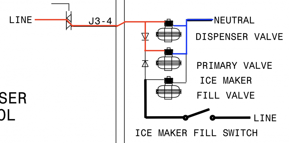
Let's look at an example of an AC circuit with a diode in it. This is the water inlet valve configuration in a refrigerator with an ice maker and a dispenser.
A very simple circuit, all told. The control is sending line voltage to both the dispenser valve and the primary valve. But you can see that there's not just one, but two diodes in this circuit! We'll focus on the top one first, but don't worry -- we'll get to the bottom one.
So what is that top diode doing? And what voltage would you measure at the dispenser valve or the primary valve?
The dispenser valve should be pretty obvious. Line connects directly to it without having to go through a diode, so you would simply read 120 VAC at the dispenser valve.
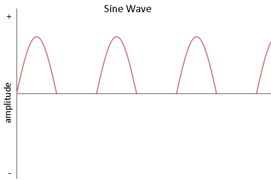
The primary valve, on the other hand, is a little more interesting. Before I tell you what you would measure at that valve, let me show you the sine wave you would get in its circuit.

Kinda funky looking, right? That diode in the primary valve's circuit is actually blocking half of the current. That's how diodes work in AC. A single diode can't block all the current like it can in a DC circuit, but it will always block half of the AC current, no matter which way the diode is oriented. The only difference orientation makes is whether the diode blocks the positive or negative side of the sine wave.
So if you were to measure the voltage at the primary valve, you would read around half of your supply voltage -- so somewhere around 60 VAC.
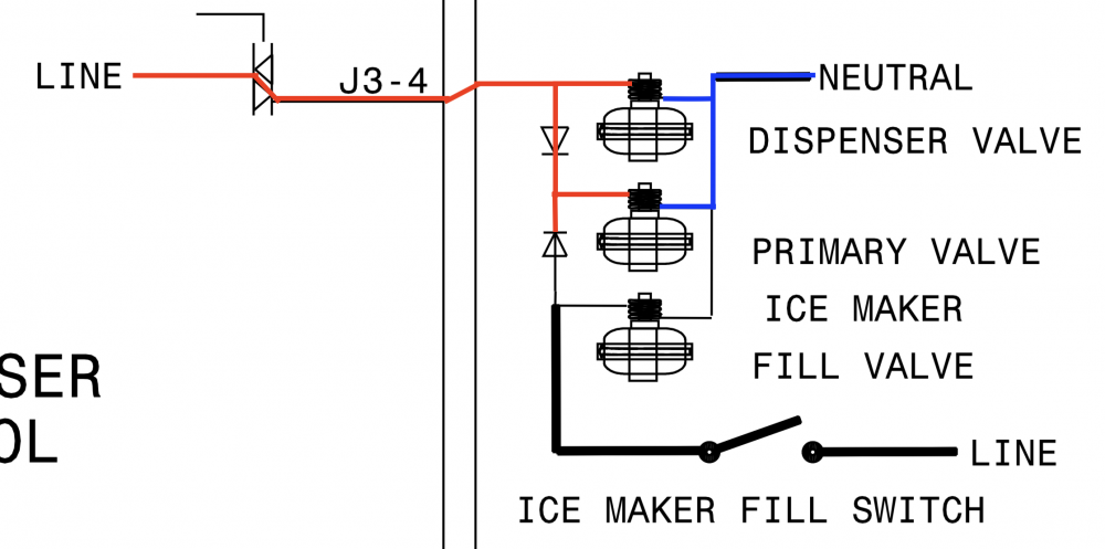
Now let's figure out what that second diode is doing. Here's that same circuit:
You'll notice that this time, I've drawn the line side extending down to the second diode, but stopping there. That second diode's function is to stop any voltage from reaching the ice maker valve when the dispenser valve is being actuated. You see, those diodes are oriented in opposite directions from each other. That means that one will block one half of the sine wave, and the other will block the other half. Together, they block out the entire sine wave.
You can see why this is by thinking back to forward-bias and reverse-bias in DC circuits. What's happening here is that each diode is forward-biased to one half of the AC sine wave and reverse-biased to the other. One is reverse-biased to the positive half, while the other is reverse-biased to the negative half. Together, they block both the positive and negative halves of the sine wave.
Now that you've seen how the circuit works, you can easily imagine how things would go if the ice maker fill switch were closed instead of the triac on the control board. In that scenario, the ice maker fill valve would get the full 120 VAC, the primary valve would get 60 VAC, and the dispenser valve would get no voltage.
Want to step your tech game up to the next level, enabling you to troubleshoot even the most complex circuit configurations with ease? Click here to enroll today in one of our online, self-paced appliance repair training courses today.
-
.png) 8
8

.png.f1622b6167220d8c8c781a7c863c9adb.png)


12 Comments
Recommended Comments