Control Board Troubleshooting: Inputs, Outputs, and Algorithms
Many techs are intimidated when it comes to troubleshooting control boards. After all, we're talking about computers here -- computers that just so happen to run appliances. But as complicated as that may sound, control board troubleshooting really boils down to just three things: measuring your inputs, measuring your outputs, and understanding the board's algorithm.
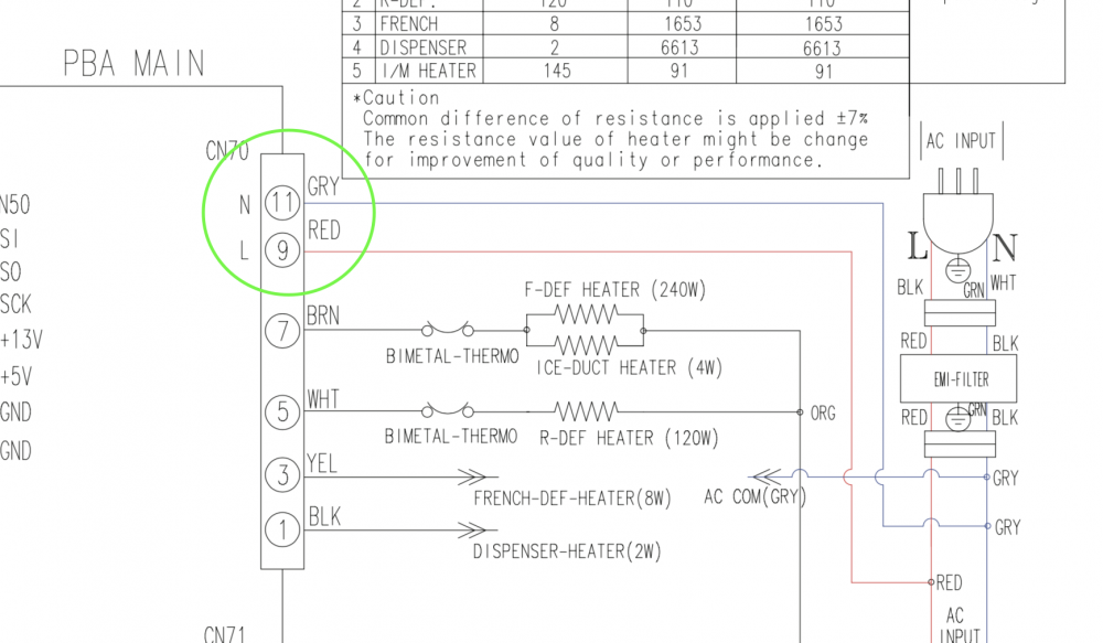
Let's start with inputs. Input just means anything, be it a power supply or some information, that the board receives from some other component. The simplest input, and the one present on every control board, is the one I've circled above -- that's just the board's line and neutral power supply. Like any electrical component, it needs both of those in order to work its magic.
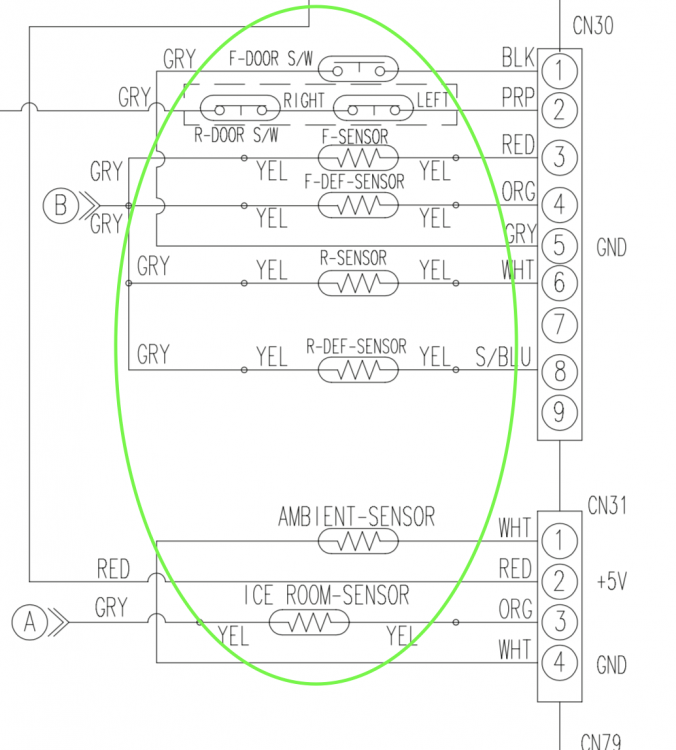
Here's a different kind of input. See all those thermistors and switches? The purpose of all of those components is to provide information to the board. The thermistors tell the board what temperature various parts of the compartments are, and the switches inform it of the state of the doors.
Inputs like this are vital for testing, since a single bad input can cause the board to make bad decisions. If an out of spec thermistor tells the board that the FF compartment is 70 degrees, then of course the board is going to run the compressor nonstop, even if this causes food in the refrigerator to freeze. That's not the board's fault -- it's just doing the best it can with the information it's given.
If you're paying attention, you'll notice something interesting. In order for the board to determine the temperature that a thermistor is sensing, it has to measure the voltage drop across that thermistor. And to do that, it needs to send voltage to the thermistor. That's right -- the board needs to issue an output to these thermistors and switches in order to receive an input from them. Speaking of outputs...
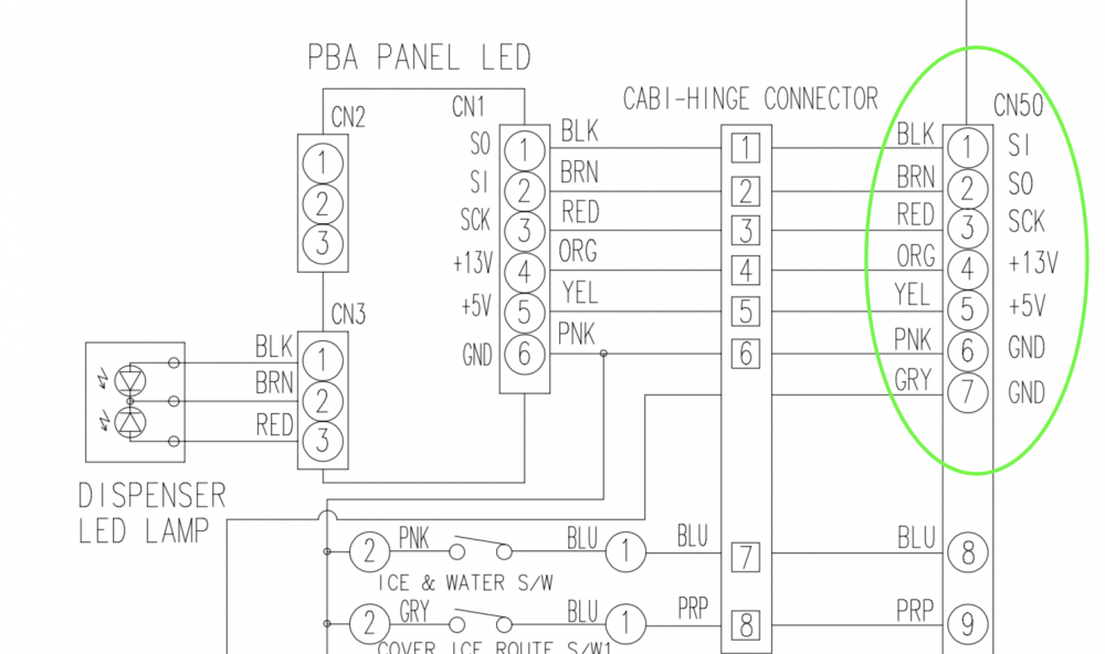
Here's a classic example of labelled outputs on a control board harness connector. That 13V, 5V, and two DC grounds are all outputs that the board is supposed to supply.
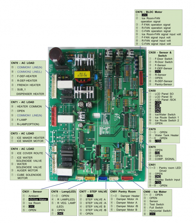
Sometimes outputs aren't labelled on the schematic, and they'll be elsewhere in the service manual -- like so:
Now that we're familiar with inputs and outputs, we can start talking about the key element of board troubleshooting. You don't have to understand every little thing that's happening on that control board -- primarily, you just need to know the inputs it's supposed to receive and the outputs it's supposed to send out.
Is the board not sending the proper output to the compressor? Make sure that it's getting the correct inputs. That means confirming its power supply, making sure the thermistors are in spec, etc. This is a classic example of using knowledge of inputs and outputs to form a troubleshooting strategy.
Does this mean that if you determine a board is receiving the correct inputs, but not putting out the correct outputs, that the board has failed? Not necessarily. There's a third element you need to be aware of: the board's algorithm.
Don't be intimidated by that word. In a nutshell, all it means is "the way the board makes decisions". The algorithm is the logic that the board operates on. Sometimes, if the board does or does not receive a certain input, it might make certain decisions about an output that aren't initially obvious to the technician.
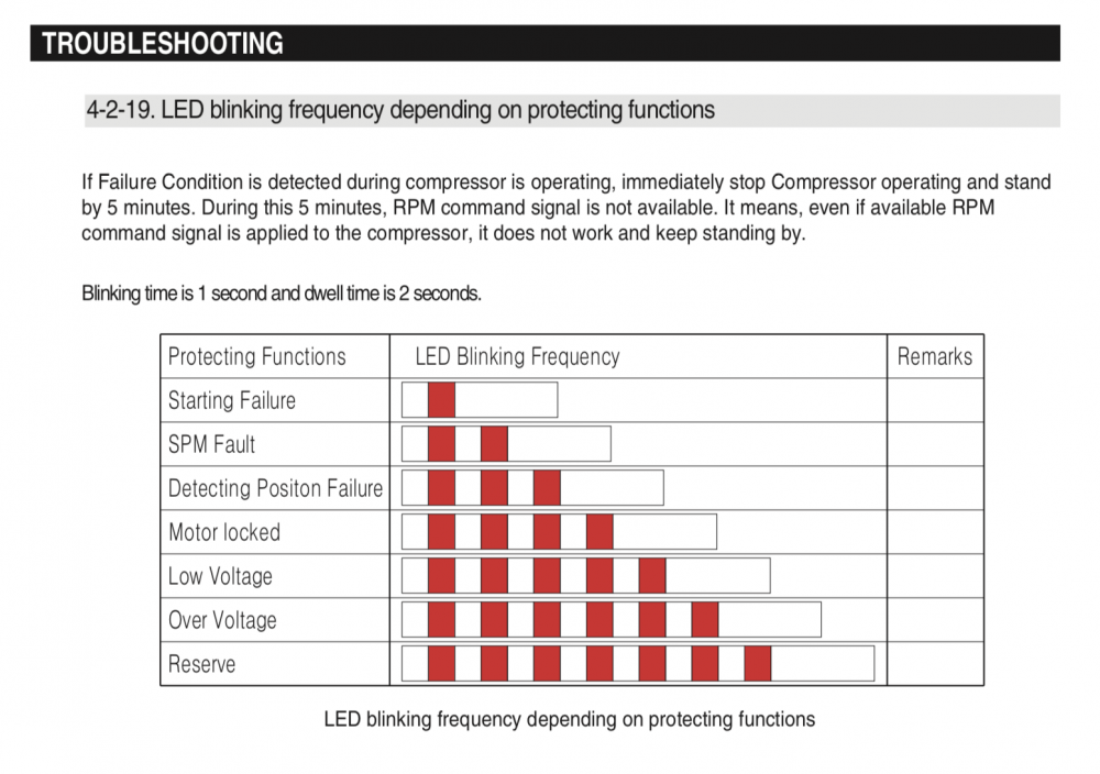
This is a good example of that. If you can parse that Korenglish, it's basically just saying that if the board receives an input saying that the compressor is not operating correctly, it will stop issuing the output of the RPM signal. The engineers who made this board programmed its algorithm to make that particular decision in this particular circumstance.
Why is this important to know? Well, let's imagine you're working on this refrigerator. You see that the compressor isn't running, so you start checking the board's outputs. Would you look at that -- the board isn't sending out an RPM signal to the compressor! Is that your problem? Must be a bad board, right?
The only way to know that the issue actually lies with the compressor is to be aware of this board's algorithm. And that means doing your homework, prediagnosing, and reading the service manual.
It really doesn't have to be any more complicated than that -- identify the inputs and outputs, and study the board's algorithm using whatever service docs you have. Those are the key steps to effective control board troubleshooting.
Want to learn more wisdom like this that will enable you to troubleshoot like a pro? Check out our online, self-paced, cutting-edge appliance repair training over at the Master Samurai Tech Academy. Click here to enroll today and learn how to troubleshoot modern, computer-controlled appliances.
-
.png) 8
8
-
 1
1



5 Comments
Recommended Comments