Start Capacitors and Run Capacitors in Split-Phase Motors
Ever seen a capacitor somewhere in a split-phase motor's circuit and wondered what exactly the point of that thing is? That's what we'll talk about in this blog post.
There are two different types of capacitors in split-phase motor circuits: start capacitors and run capacitors. Each type has a different set of parameters and serves a different purpose. But before we get into these specific types of capacitors, let's take a quick review on capacitors in general.
Capacitors aren't complicated devices. At their most basic, they're just two conductive plates that are separated from each other by an insulator so that no current can flow between the plates. They act as charge-holding devices, meaning that they can store voltage much like a battery.
Because of that insulation, you'd think that a capacitor would create an open in any circuit that it's in, and you'd be right — but that’s not the end of the story.
In a DC circuit, voltage only has one polarity. When voltage is applied to a capacitor, it begins to store a charge up to what it can hold (its capacitance, which is measured in microfarads). Once it reaches its max, the capacitor stops charging, current stops flowing, and the DC circuit is effectively open.
However, in AC circuits, the polarity of the voltage is constantly reversing. The capacitor will still charge up, but then once the voltage swaps polarity, it will discharge, the electrons will circle around to the other side of the capacitor, and it will begin to charge again, but with the opposite polarity. And so on, back and forth, for as long as voltage is applied. The capacitor is still an open in the circuit, but because of AC’s rapidly changing polarity, the current can get around it.
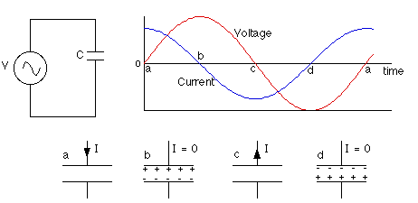
This constant charging and discharging in AC circuits makes for some interesting properties. The one that's of most interest to us here is capacitive reactance. Without getting too into the weeds, you can think of this as a kind of resistance caused by the capacitor charging and discharging. More precisely, capacitors resist changes in voltage, causing the voltage sine wave to lag behind the current sine wave in the circuit. The image below nicely demonstrates the activity of a capacitor in an AC circuit.

If you're unfamiliar with sine waves and the fact that current and voltage sine waves can become out of sync, you should click here to read my previous post on induction in split-phase circuits. It will help you understand what I'm talking about in the rest of this post.
Those of you who read that blog post carefully might notice that inductors, such as motor windings, have the opposite effect of capacitors. While capacitors cause voltage to lag behind current, inductors cause current to lag behind voltage.
Now that you know how capacitors work, we can get into start and run capacitors.
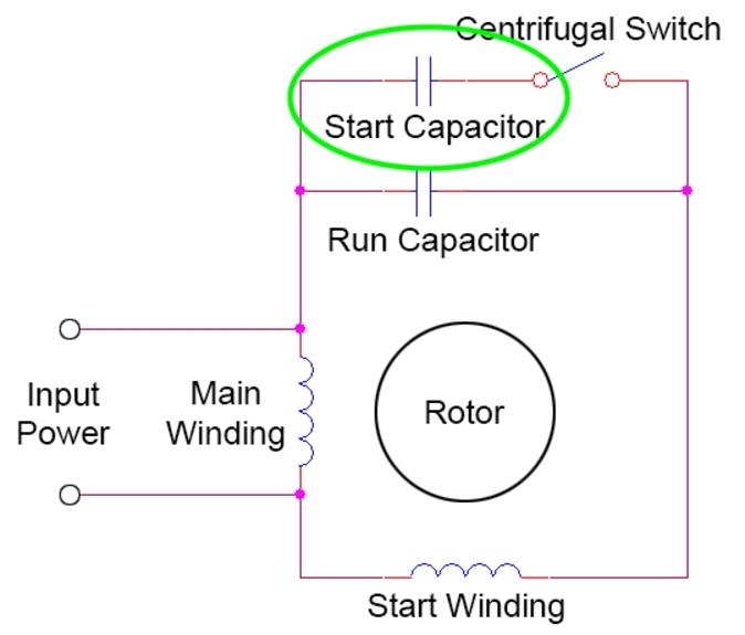
Start capacitors: As you might expect from the name, start capacitors are located in series with the start winding of a split-phase motor.

Because it's in the start winding's circuit, it's only energized until the centrifugal switch takes it out of the circuit. But during that short time, it makes a big difference.
Remember how the purpose of the start winding is to create a second phase of current that will give the motor the kick it needs to get going from a dead stop? Well the start capacitor takes that to the next level. Using its capacitive reactance, the capacitor increases that phase separation even further, providing a large increase in starting torque. There's a reason you tend to see start capacitors on motors that need to more heavy loads.
Start capacitors are designed to hold and release a large amount of charge. They're made with high capacitance, often getting up to 430 - 516 mfd. (Microfarads can be abbreviated variously as mfd, uf, and μF.) But because they hold so much charge, they're also only designed to operate for a short period of time -- just a few seconds. And that's fine, because they're only supposed to stay in the circuit for as long as the start winding does. If the centrifugal switch fails to open, you're very likely to have a follow-on failure in the form of an exploded start capacitor.
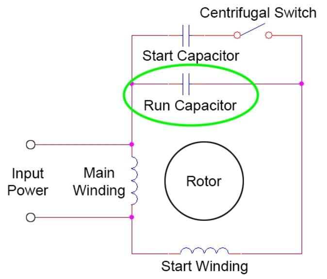
Run capacitors: Despite what you might expect from their name, run capacitors are actually parallel to the run (or "main") winding, not in series with it. But unlike the start capacitor, the run capacitor is kept in the circuit the entire time. They also have much less capacitance: generally in the range of 5 -15 mfd.

It's not concerned with starting torque, but more rather with increasing the motor's efficiency while it's running. It does this by improving the motor's power factor.
We don't need to get too bogged down with all the specifics of power factor, but I want to give you at least a functional understanding of it so that you can get a sense of what run capacitors do. Power factor describes how much of the power the motor uses is being used for useful work. A power factor of 100% would be the ideal, since that means 100% of the power that's provided to the motor produces work. But since there's always some wasted power, that's not possible. More often we see something like 75% or 80% -- meaning 25% - 20% of the power supplied to the motor is wasted.
Because they put voltage and current out of phase with each other, inductive components like motor windings reduce the power factor of a circuit. Run capacitors help to trim down on that waste a little, and they do this by virtue of the fact that they're the opposite of inductors. When you put a capacitor with the proper specs in parallel with an inductor, it helps to improve the power factor and reduce waste.
Run and start capacitors are only one way that capacitors can be used in motor circuits. Interested in learning more about the technology in appliances, how they work, and how to troubleshoot them? We teach all this and more in the Core Appliance Repair Training Course at the Master Samurai tech Academy. Learn more, earn more.
-
.png) 9
9
-
 1
1

.png.62a7d7300de75dfbd19764a318766630.png)


4 Comments
Recommended Comments