Jump to content
Click here to check out this guide.

FAQs | Repair Videos | Academy | Newsletter | Contact


Samurai Appliance Repair Man's Blog

  • entries
    861
  • comments
    1,408
  • views
    3,411,906

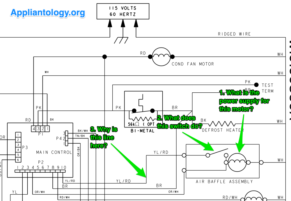
How does the air baffle assembly work in this refrigerator?


image.png


1. Which wires are the power supply circuit for the damper motor? 

2. What does that switch by the damper motor do? 

3. What's with the line going from one side of the switch back to the board? 


Hint: This is a dead simple circuit. The motor does not reverse direction of rotation. The schematic alone tells you everything you need to know. You do not need any additional “inside baseball.”  

Don't let me down, comrades. First one to answer all three questions correctly wins an all-expenses paid virtual dinner with Miss CSR 2022!


  • Like 1
  • Haha 2

14 Comments


Recommended Comments

  • Team Samurai
Samurai Appliance Repair Man

Posted

No takers on this? Where are all the electronics whiz kids sporting the hi-tek gizmodos and circuit board repair porn? This should be like grade school stuff for you guys. C’mon, help a brutha out!  

Terry Carmen

Posted (edited)

The board runs the motor until the switch (and the air door) is in a position that it likes (open or closed).

Edited by Terry Carmen
  • Like 1
Rich Armstrong

Posted

1: 120 V ac   2: Single pole double throw Switch NO  3:  P2 10 provides 120 V ac reverse polarity to shaded pole motor and closes baffle door to the FF compartment 

  • Like 1
  • Team Samurai
Samurai Appliance Repair Man

Posted

5 hours ago, Terry Carmen said:

The board runs the motor until the switch (and the air door) is in a position that it likes (open or closed).

Good start. But how does the switch opening or closing affect the motor operation? 

  • Team Samurai
Samurai Appliance Repair Man

Posted

2 hours ago, Rich Armstrong said:

1: 120 V ac

Supplied by which wires?

2 hours ago, Rich Armstrong said:

2: Single pole double throw Switch NO  

But how does this switch affect motor operation?

2 hours ago, Rich Armstrong said:

3:  P2 10 provides 120 V ac reverse polarity to shaded pole motor and closes baffle door to the FF compartment

Reverse polarity from 120VAC? But AC voltage is already reversing polarity 60 times a second. Is the board making a double extra special phase inverted AC? And how does that work if one side of the motor is always tied to Neutral? Dang pesky details! 

  • Haha 1
David C

Posted (edited)

1. 120vac or/w L1  and white N

2. Switch opens and closes based on damper position.

3. Provides input to the control based on damper position, which will switch power on and off to the damper motor.

Edited by David C
  • Like 3
  • Team Samurai
Samurai Appliance Repair Man

Posted

1 hour ago, David C said:

1. 120vac or/w L1  and white N

2. Switch opens and closes based on damper position.

3. Provides input to the control based on damper position, which will switch power on and off to the damper motor.

There's the tech mojo I was looking for! I knew someone on this venerable forum had it. 

Extra credit questions:

1. What is the functional name for these types of switches that get actuated by a specific range of motion? We see these in oven door latch assemblies and snorkel vents that raise and lower. 

2. What is the functional name of these kind of switched lines that provide input to a control board? We see this all over the place in appliances with control boards ranging from medieval ones like this ADC controller to full-blown computers. 

3. Given that the damper motion must stop immediately in precise locations, what type of AC motor do you think they're using for the damper motor? Hint: shaded pole ain't one of them. 

David C

Posted

Synchronous 

  • Like 2
  • Team Samurai
Samurai Appliance Repair Man

Posted

Just now, David C said:

Synchronous 

Yep! Just like with timer motors and oven door lock motors. 

tonkyman79

Posted

1. Limit switch

2. Logic


  • Like 1
  • Team Samurai
Samurai Appliance Repair Man

Posted

41 minutes ago, tonkyman79 said:

1. Limit switch

Yep! 
 

41 minutes ago, tonkyman79 said:

2. Logic

Its input is used by the logic on the board, that’s true. The line itself is not logic since it is toggling AC voltage. The board is sensing this toggled voltage and making logic or algorithmic decisions about when to supply and remove power to the load (damper motor). So the line itself is a sensing line

  • Like 1
Dragan Panic

Posted

signal line;

positioner switch;

step motor, or could be motor with worm type of gear.

  • Team Samurai
Samurai Appliance Repair Man

Posted

21 minutes ago, Dragan Panic said:

signal line;

positioner switch;

Close enough. They're usually called "limit switches" and "sensing lines" but you got the idea. 

21 minutes ago, Dragan Panic said:

step motor, or could be motor with worm type of gear.

Wouldn't be a stepper because the schematic only shows one winding. Plus this is an old skool fridge, before they started using steppers in things like three-way valves. With this type of limit switch and sensing line control scheme, you don't need to spend the money on an expensive stepper motor when a cheap old synchro will git 'er done. 

Dragan Panic

Posted

Simple is usually better, I agree. Thanks!

×
×
  • Create New...