Jump to content
Click here to check out this guide

FAQs | Repair Videos | Academy | Newsletter | Contact


Appliance Repair Tech Tips

  • entries
    220
  • comments
    728
  • views
    250,374

How Does the Lid Lock Circuit Work in a Top-Load Washer?


Son of Samurai

6,797 views

Let's crack out our schematic-reading skills and take a look at a seemingly straightforward washer lid lock circuit.

36994997-E901-41B9-AB1F-3C9EF51266FA.jpeg.43b1805d370e6cdae365711623ba360b.jpeg

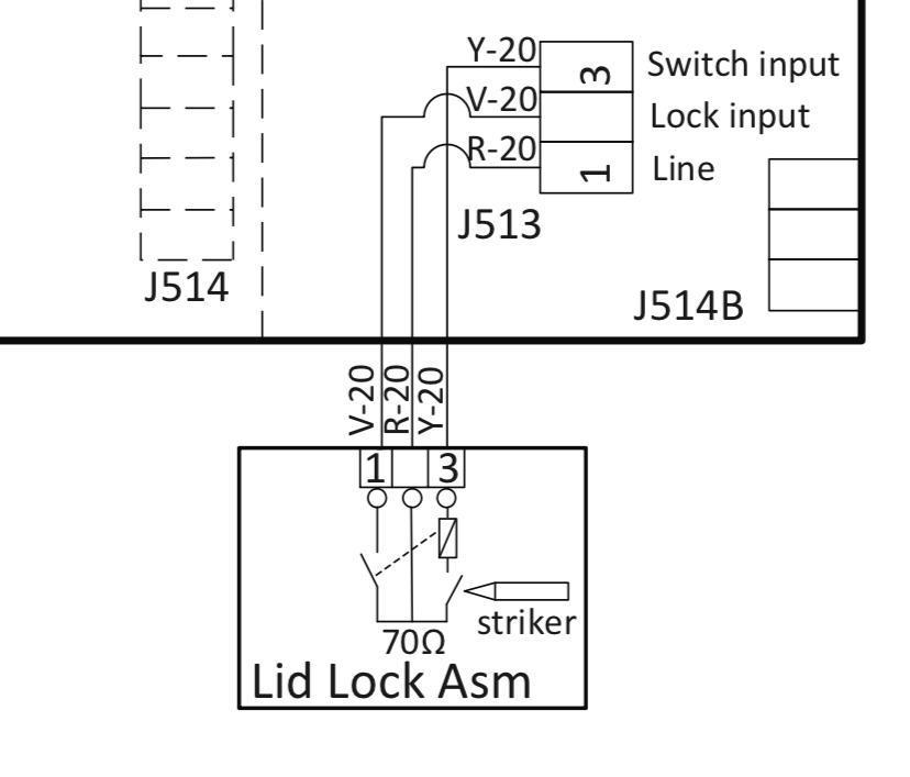
Notice that, while they give us labels for the pins, that's basically all we've got as far as specs or info about the control board's algorithm. So if we want to figure out how this circuit works during operation, we'll have to crack out some Circuit Fu™. That means using both our understanding of electricity and our understanding of the intended function of a lid lock to deduce how the circuit must work.

When the machine is in standby and the lid is open, this is what the circuit would look like:

36994997-E901-41B9-AB1F-3C9EF51266FA_jpeg_43b1805d370e6cdae365711623ba360b.jpg

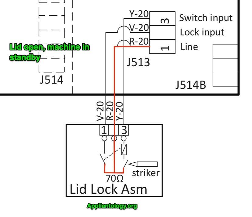
Intuitive enough -- you have Line supplied to the circuit from J513-1, but it's just standing at those open switches. There's no complete circuit for that voltage to drive current through.

Let's take a look at what happens when the lid is closed. Note that the "striker" is just what it seems -- that's the tongue sticking down from the lid. It actuates the switch it's pointing at in the schematic by physically pushing down on it when the lid is closed.

36994997-E901-41B9-AB1F-3C9EF51266FA_jpeg_43b1805d370e6cdae365711623ba360b-2.jpg

Okay, so now the lid is closed, and the striker has closed the right-hand switch. Now, we have Line present all the way up to J513-3.

Pop quiz: how much current is now going to be flowing through that wire?

None? Wow, spot on! Didn't know you were sharp like that. There's no neutral supply to the circuit yet, and therefore it's not a complete circuit. No current can flow yet.

So what does Line voltage being present at pin 3 accomplish, then? It lets the control board know that the lid is closed. In other words, it's a sensing line. The control has a little voltage sensing circuit set up at that pin, and it's constantly poling it to see if Line is present. Once it senses Line, it knows that the lid is closed

Next up: what happens when the customer starts a cycle?

36994997-E901-41B9-AB1F-3C9EF51266FA_jpeg_43b1805d370e6cdae365711623ba360b-3.jpg

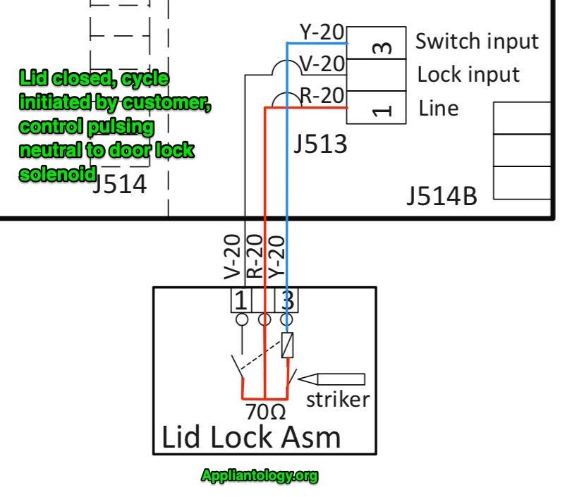
Suddenly, that sensing line at pin 3 isn't just a sensing line anymore -- it's a Neutral supply! What's happening here?

First off, that rectangle just above the lid switch is the lid lock solenoid. When that solenoid is energized, it actuates the left-hand switch -- the one it's connected to by a dashed line. Here's a tricky bit about this that you only get from being familiar with this kind of lid lock technology: the control only supplies Neutral to the lid lock solenoid for a short moment. It's just a quick pulse, and then the Neutral supply is gone again. This is because the lid lock switch that the solenoid actuates is a toggle switch. Give the solenoid a pulse of power and that switch pops closed. Give it another pulse, and it pops open.

So the circuit will only be in the state as shown above for a fraction of a second, but that's plenty long for the solenoid to do its job and actuate the other switch. And once that's done, we'll have the following state:

36994997-E901-41B9-AB1F-3C9EF51266FA_jpeg_43b1805d370e6cdae365711623ba360b-4.jpg

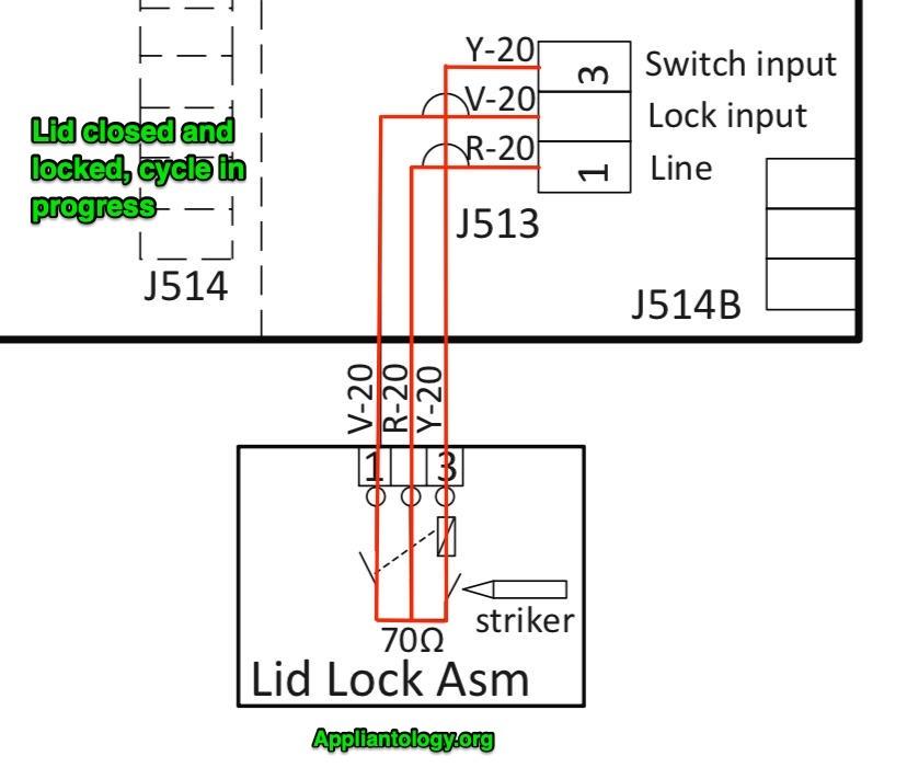
The board has cut off its quick pulse of Neutral to the lid lock solenoid, and the solenoid as done its job: the lid lock switch is closed. And the board can tell that the solenoid has done its job by poling for Line voltage at J513 pin 2 -- voltage will only be present there if the lid lock switch is closed.

Now that the lid has been locked and, just as important, the control knows that the lid has been locked, the wash cycle can progress.

Want to learn more about reading schematics and figuring out how circuits like this work? Click here to check out our Core Appliance Repair Training Course over at the Master Samurai Tech Academy.

  • Like 18
  • Thanks 1

14 Comments


Recommended Comments

 I had to read it a couple of times to understand it but I got it..

  • Like 2
Link to comment

Fantastic article. I took the course and I have a profitable business after taking it.

  • Like 2
Link to comment

Thanks for the knowledge, Gurus... much appreciated.  Will implement my better understanding in the field!!

  • Like 2
Link to comment
Rich Armstrong

Posted

How did you figure this out Samurai? This specific lid lock has given me grief a handful of times, causing me to fail at repairing the washer and embarrassing me! The Service Manual offers two choices… 1 The Lid Lock has failed ( it ALWAYS passes the test ) 2 Main circuit board has failed. Thanks for sharing this information. My anxiety level will be lessened next time around. Thank you 🙏🏻 

  • Like 2
Link to comment

Beginner question, You wrote this "So the circuit will only be in the state as shown above for a fraction of a second, but that's plenty long for the solenoid to do its job and actuate the other switch."

On a job would I be able to test this from the J513 section of the board not sure what I would be seeing Voltage wise if the Neutral is on for a split second.

Link to comment
dfphoto

Posted (edited)

Would I be looking for Current? 1.7A , 119VAC I've never tried to test a lid switch so not sure what you all look for. At Y20-V20

Thanks David

Edited by dfphoto
Link to comment
Rich Armstrong

Posted

I took a Reliable Whirlpool laundry class this morning. A bit boring at first but a did pick up a couple nuggets. The new lid lock assembles now have four wires. Could you please do a mini seminar on this Son of  Samurai? 

Link to comment
  • Team Samurai
Samurai Appliance Repair Man

Posted

13 hours ago, dfphoto said:

On a job would I be able to test this from the J513 section of the board not sure what I would be seeing Voltage wise if the Neutral is on for a split second.

Set your meter on Min/Max setting and it will catch voltage readings that are too fleeting for the display to show. 

  • Like 1
Link to comment
  • Team Samurai
Samurai Appliance Repair Man

Posted

13 hours ago, Rich Armstrong said:

The new lid lock assembles now have four wires. Could you please do a mini seminar on this Son of  Samurai? 

Interesting! Might make a good show 'n tell at a Live Dojo. Do you have a model number so we can pull the schematics and see how little they're telling us about the circuit? ;)

  • Like 1
Link to comment

Follow up,  if I was on a job and looking at the lid switch, if the solenoid gave me the VAC via the  Min/Max setting = the switch is good

R20-Pin 1 = Line VAC +70Ω R

Y20 Pin 3 = Sensing V and after the Solenoid kicks = N

V20 Pin 2 = Lock Imput switch if there is Voltage from Y20 Pin 3 = Closed IF NO Voltage = Open

I'm a tad confused about the 70Ω R if the solenoid sends V and no run would I go back and look at other LOADS in this circuit, but if there is no V via the Solenoid would I then look at the 70Ω R?

Or would I conclude the switch is bad. Appreciate your help in advance.


Link to comment
Rich Armstrong

Posted

On 8/11/2023 at 9:43 AM, Samurai Appliance Repair Man said:

Do you have a model number so we can pull the schematics

I do not have a model number unfortunately! 

Link to comment
×
×
  • Create New...