.png.aa21533c6656a1cb054a172848652cb2.png)
How does this old skool dishwasher drain the water?

Entry posted by Samurai Appliance Repair Man in Tech Talk
2,263 views
Y'all grab a cold one and gather 'round-- crusty ol' Samurai's gonna tell you a story. This here's a story about one o' them old skool dishwashers like yo momma had when you were still but a glimmer in yo pappy's eye.
These old skool dishwashers didn't have a separate, dinky little drain pump motor like today's gelded dishwashers. Nawsir, these old skool dishwashers had just one big honkin' motor that did double duty washing (more like sandblasting) the dishes and draining the basin. They did this by making the motor spin either CW or CCW. But what really tickled my eyeballs was the way they did this. Those old skool engineers were really clever with using simple circuits and switches.
The circuit skills required to understand and troubleshoot these old-skool machines are also needed for the computerized geldings of today with their two dinky motors for wash and drain. So let's do some learnin' by taking a look at the motor control circuit in these old war horses and see how real dishwashers got 'er done.
FYI - the dishwasher we're looking at is the venerable old Whirlpool platform.
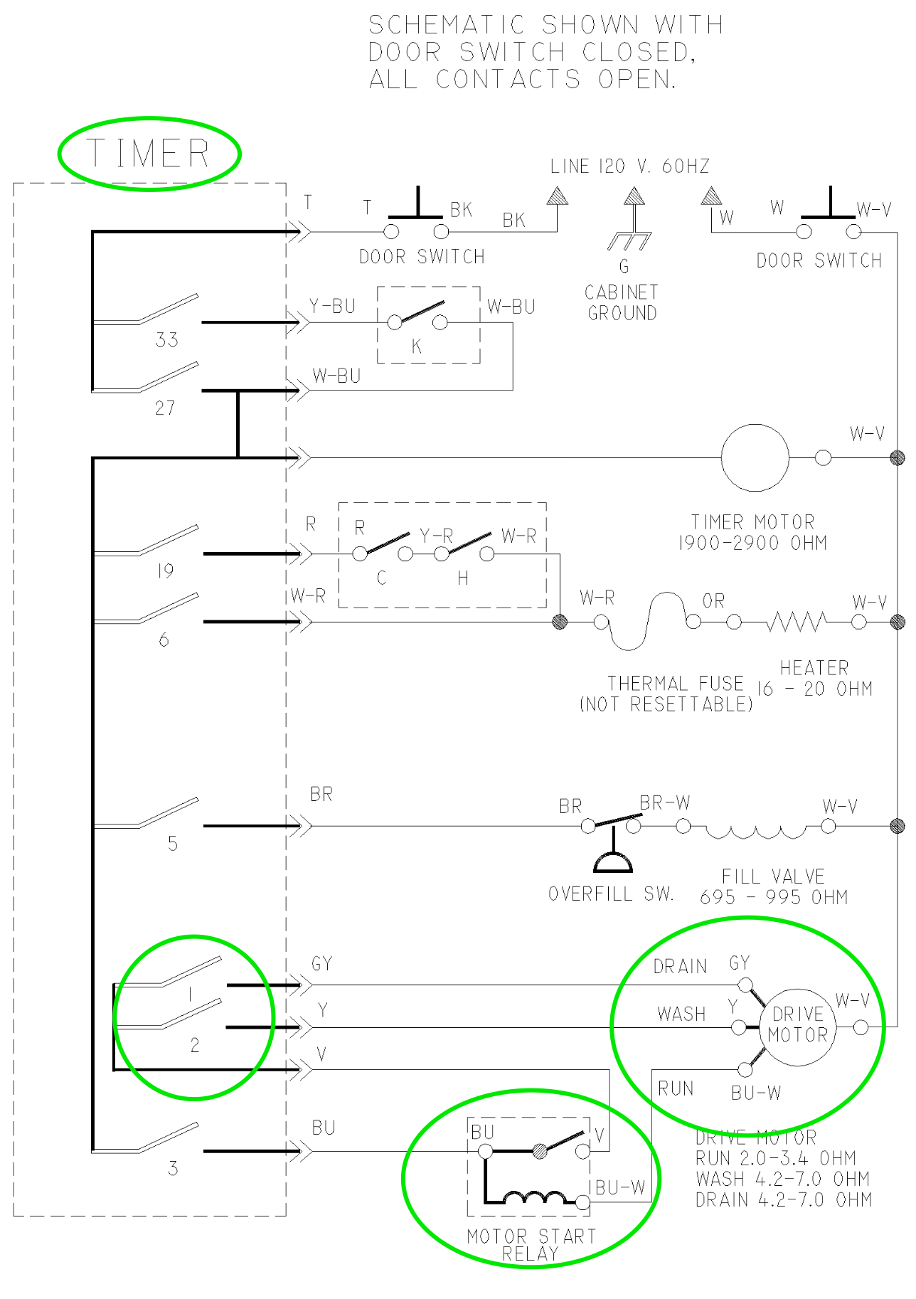
As you can see, we got one bigazz motor with two different start windings, drain and wash, and a single run winding. This is what we call a "split phase AC induction motor" and like all split phase motors, you need a start winding that helps the rotor get spinning from a dead stop. After that, it's taken out of the circuit by a switch; in this case, a current relay (these are special animals-- stay tuned, we'll get to it).
I know what you're axin, "But why are there two start windings and how do they affect the motor?" Good question!
Each start winding is physically wound to present a different magnetic polarity to the run winding. That polarity in relation to the run winding is what determines the start direction of the rotor. So one of the start windings, say drain, is wound such that it will spin CW, and similarly, the other will make it spin CCW from a dead stop. (It may be the other way around but that's not the point. Focus please!)
Okay, so how does that motor know to run either CW or CCW? It doesn't, it's just a dumb motor. The start direction is controlled by the timer. The timer is an old skool way of doing what computers do in today's appliances: executing what we call an algorithm. Algorithm is just a fancy word that means "the intended operation of a machine." Algorithms can be mechanical, electrical, electronic or any combination. Whatever the engineers decide to use. Where computers execute an electronic algorithm using software, timers execute an algorithm mechanically using a spindle and switches. Part of the timer's algorithm is when to run the motor in drain or wash.
When the timer contact 3 closes, it sends L1 to the motor start relay coil. The motor start relay is a current relay that sends L1 to the Run motor winding (through the relay coil) and the large in-rush current creates a large magnetic field that closes the motor relay switch. The now-closed motor start relay switch also sends L1 to either the Drain or Wash motor winding depending on which timer switch is closed: If switch 1 is closed, you get drain; If switch 2 is closed, you get wash. Once the motor gets up to speed, the current through the relay coil drops and the resulting magnetic field decreases so the relay contacts open. This removes the start winding from the circuit and the motor continues to run on the Run winding. Is that some elegant circuit fu, or what?
So how do you troubleshoot this if the motor is not running in drain? Since we know from the schematic that timer switch 1 has to be closed to run the motor in drain, all we need to do is test to see if switch 1 is closed in drain. Two ways to test this:
- Continuity. Turn the timer knob to drain position where you know switch 1 should be closed. This is tricky because the timer chart for this one does not show an initial pumpout like on newer dishwashers. So... good luck with that. I only include it here because it's theoretically possible (albeit impractical) and most techs just love ohms and continuity. I mean, what else do you need to know 'bout 'lectricity?
- Voltage. Set your LoZ voltmeter probes at the GY wire on the timer and the unswitched Neutral wire on the door switch. Start a cycle and advance to drain to see if you're getting L1 between timer switch 1 (gray wire) and Neutral (door switch, white wire, conveniently located in the same control console) when the motor should be running in drain. If you don't see 120 VAC there, then timer switch 1 is open.
See the power of reading the schematic and understanding what's going on in a live circuit? Reading a schematic does not mean simply looking at the pretty lines and symbols. Reading a schematic means you're seeing how electrons move in the circuit to make loads do their jobs. This is the high-dollar skill that goes on inside our heads. We make it easy and teach you how in the Core course at Master Samurai Tech.
-
.png) 8
8
-
 1
1

1 Comment
Recommended Comments