Jump to content
Click here to check out this guide

FAQs | Repair Videos | Academy | Newsletter | Contact


Appliance Repair Tech Tips

  • entries
    220
  • comments
    728
  • views
    250,379

Schematic Basics: LG Wall Oven No Heat


Son of Samurai

2,783 views

Got a short and sweet one for you today. Here's the scenario:

You're troubleshooting an LG wall oven that doesn't heat. You've gone ahead and torn it down as much as you could to do an ohms measurement on the broil element (in spec) and the temperature sensor (also in spec). You confirmed that the unit was getting a good 240 VAC power supply. You wanted to test the bake element too, but you didn't have a second man with you, so you gave up on that idea. Instead, you just replaced the main control board and hoped that would get it.

Unfortunately, you didn't win the lotto this time, and now you're out a control board. What did you do wrong in your troubleshooting, and how could you have done it better?

A couple key issues with your troubleshooting strategy so far: relying on ohms measurements over more reliable voltage or amp tests and performing unnecessary disassembly to do tests. These are PCM moves. To troubleshoot this like a real tech, we need to take the first step any real tech does and look at the schematic.

image.thumb.png.b6feb8ec851d460628ba75ac34582adb.png

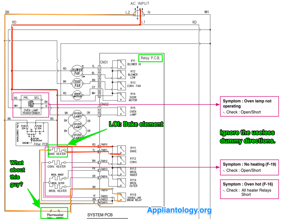
Now that we're looking at the schematic, things become much plainer. I'll explain a couple of terms in the markup.

The LOI is your Load of Interest. That just means it's the load that's not doing what it's supposed to be doing. In this case, we actually have multiple potential LOIs, since all of our elements aren't heating. But that's not a problem -- we just pick one, like the bake element, and make that our LOI. Then we analyze its circuit.

Dummy directions are those pink boxes to the side. These are rarely useful in any tech doc, and these particular ones are extremely unhelpful. Just ignore them.

Now that we're looking at things sensibly, you'll notice that the bake element can be tested right from the relay board, which is pretty easily accessible. No second man required. One meter lead on the bake relay and the other on the DLB relay lets us measure the voltage in the bake element's circuit -- simple as that. If we have a good 240 VAC supply while the oven is on, then we know the relay board is doing its job. That would only leave the bake element as the culprit. But it's very unlikely that that's the case, since all of the elements aren't working. This means we need to find something that has failed which is common to all of them.

You could have a failed DLB relay on the relay board -- but that's not the only possibility. Since we've done a thorough circuit analysis of the LOI's circuit, we've noticed that there's a thermostat in the L2 leg of its power supply. If that's gone open, it will cut off L2 to all the elements.

Yet again, there's no need to disassemble -- a simple test for the presence of voltage at the DLB relay will tell us if the thermostat has gone open or not. And just like that, we're able to positively identify a failed component without any more disassembly than it took to get to the relay board.

Want to learn how to read schematics and troubleshoot like a real tech? Click here to check out our Core Appliance Repair Training Course over at the Master Samurai Tech Academy.

  • Like 10
  • Thanks 1

11 Comments


Recommended Comments

  • Team Samurai
Son of Samurai

Posted

5 hours ago, Samurai Appliance Repair Man said:

@Son of Samurai - Why do you call them Dummy Directions®?


‘Cause if you follow them, you’re a dummy!

  • Haha 3
Link to comment

Thanks for the tips!  Piling on the knowledge!!  

Link to comment

@Son of Samurai Hi Sam, wondering if you can expand a little on this LG schematic, I don't understand how I would decipher how L1 changes on the PCB and then goes to a relay board.

In my picture the bottom Red wire is L1 goes around through the Thermostat, goes into SMP5 Pin 1 goes into a board SMPS PCB into the Main PCB board. There I am looking for areas that could be a problem for my No Heat complaint. (I know most of the time it is the igniter but this is a 4 month call back where I replaced the igniter). Looking for my plan B troubleshooting, I need (for confidence) to have knowledge how to trace better).

Temp Probe, Oven Sensor, Door Switch, then to another board the Relay PCB then to my Igniter. How do I tell which of the two wires on the Temp Probe, Oven Sensor, Door Switch is L1 or DC voltage. This happens to me a lot and I never got a straight answer.

Also on SMP5 Pin 3 the Neutral when I see the wires this is dumb but when I see this it always means the wire is continuing whether N or L1 or DC?

Appreciate the answers....

Screen Shot 2023-11-14 at 11.21.17 AM.png

Screen Shot 2023-11-14 at 11.32.14 AM.png

Link to comment
On 6/14/2023 at 7:47 AM, Samurai Appliance Repair Man said:

@Son of Samurai - Why do you call them Dummy Directions®?


If we need to test the thermostat we measure voltage drop across it if 0 vac  that’s mean the thermostat is good if 120 v that means the thermostat is open ?

Link to comment
dfphoto

Posted (edited)

@Son of Samurai, I meant I'm dumb not understanding...... BTW if you look at the main system pcb this is where I am 100% lost on schematics I have no idea where L1 or DC Voltage is going on the door lock switch or the door switch.

Edited by dfphoto
Link to comment
  • Team Samurai
Samurai Appliance Repair Man

Posted

On 11/14/2023 at 2:33 PM, dfphoto said:

In my picture the bottom Red wire is L1 goes around through the Thermostat, goes into SMP5 Pin 1

That’s SMPS, not SMP5. SMPS stands for “switch mode power supply”— a type of programmable DC power supply. DC power supplies convert AC into DC. It’s outputs and communications with the main computer are on CN02. There are lots of components and circuitry between CN01 and CN02 on the SMPS board that are not shown. They are showing the SMPS as a “black box” with inputs and outputs. So you don’t read L1 going into CN01 and then look for L1 coming out CN02 because there’s a whole lot of circuitry between CN01 and CN02.

On 11/14/2023 at 2:33 PM, dfphoto said:

Also on SMP5 Pin 3

Incorrect callout. Neutral is supplied to the SMPS at CN01-3. It is then “daisy chained” to TAB25 on the relay board. 

Link to comment
  • Team Samurai
Samurai Appliance Repair Man

Posted

3 hours ago, Madison said:

If we need to test the thermostat we measure voltage drop across it if 0 vac  that’s mean the thermostat is good

More precisely, the thermostat is closed.

3 hours ago, Madison said:

if 120 v that means the thermostat is open

Yes. 

  • Like 1
Link to comment
  • Team Samurai
Samurai Appliance Repair Man

Posted

5 hours ago, dfphoto said:

I have no idea where L1 or DC Voltage is going on the door lock switch or the door switch.

We need a pinout diagram to know the exact voltages going to these components. But the oven sensor and temp probe will usually be DC voltages. The door lock could be either AC or DC. We aren’t given enough info in the schematic to know for certain. 

Link to comment
×
×
  • Create New...