
Using Schematics and Wiring Diagrams to Figure out Why the Lights Won't Turn Off on this GE Wall Oven

Entry posted by Son of Samurai in Tech Talk
5,620 views
At one of our recent Live Dojo workshops, a tech shared an interesting problem he had encountered.
He was called out on a GE wall oven where the upper oven lights stayed on all the time, and the door lock wouldn't activate. He investigated further, discovering that when he opened and closed the lower oven door, he heard a relay click as the light turned on and off — but there was no such relay sound for the upper oven.
Presuming this meant a stuck relay on the control board, he went ahead and replaced the board. However, the problem persisted. Only then did he find something else: a pinched wire harness going to the door lock assembly. After replacing this harness, the symptoms disappeared. How is this possible? Is there some combination of broken wires in the pinched harness that would cause the relay for the oven light to stay closed and the door lock motor not to work?
Let's take a look at the tech sheet to figure out how this could happen.
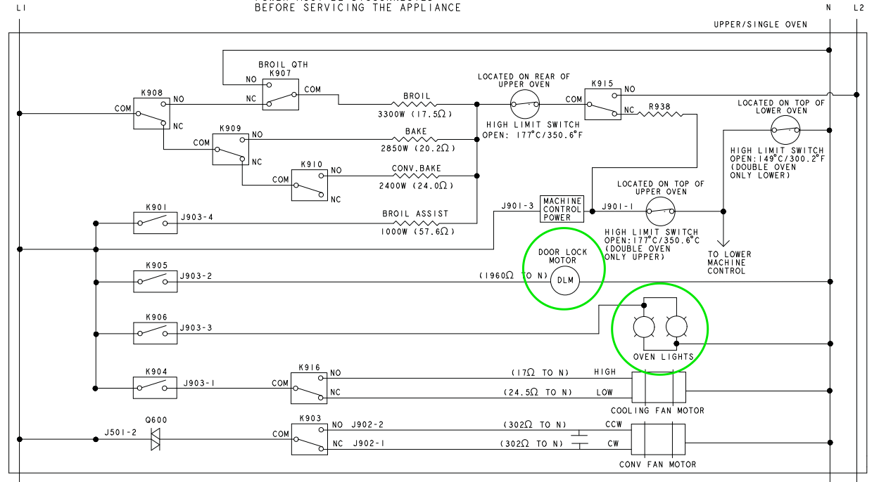
Schematic of Upper Oven
Here's the schematic of the upper oven with the door lock motor and the oven lights circled. These are our Loads of Interest.
If we analyze their power supplies to see how they get Line and Neutral, it looks like this:
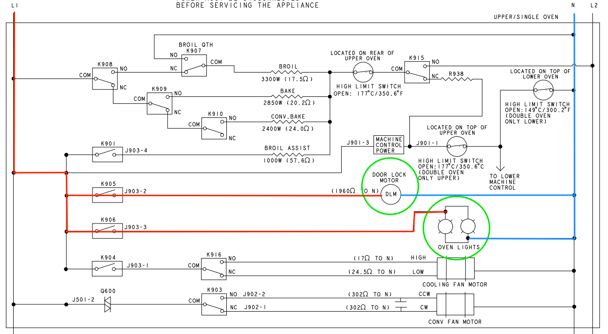
That's about as straightforward as it gets. Each of our LOIs has an unswitched, direct connection to Neutral. L1 is provided on the other side by a relay, one relay for the door lock motor and the other for the lights. These relays are directly controlled by the computer board.
These two circuits are completely parallel to each other. Maybe the door lock motor’s lack of operation could be explained by a broken wire in its circuit, but that wouldn’t explain the light staying on at all.
Wiring Diagram
Since we’re dealing with a wiring problem here, we have to go to another part of the tech sheet: the wiring diagram. Unlike the schematic, the wiring diagram shows us the physical layout of the wires and harnesses in the machine.
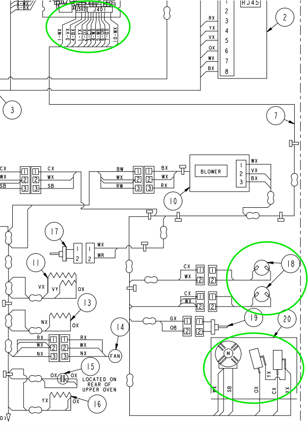
Kinda gnarly looking, right? To help you make sense of this, I've circled what we're interested in. At the top is the connector where our pinched harness meets the control board. The loads numbered as 18 are the lights, and the assembly marked as 20 is the door lock assembly.
So how do we read this diagram? What we're interested in finding out is what circuits could possibly be interrupted by our pinched harness. This diagram shows each harness as a single line. Individual wires only separate from this harness on the diagram when they are headed to a load or a switch.
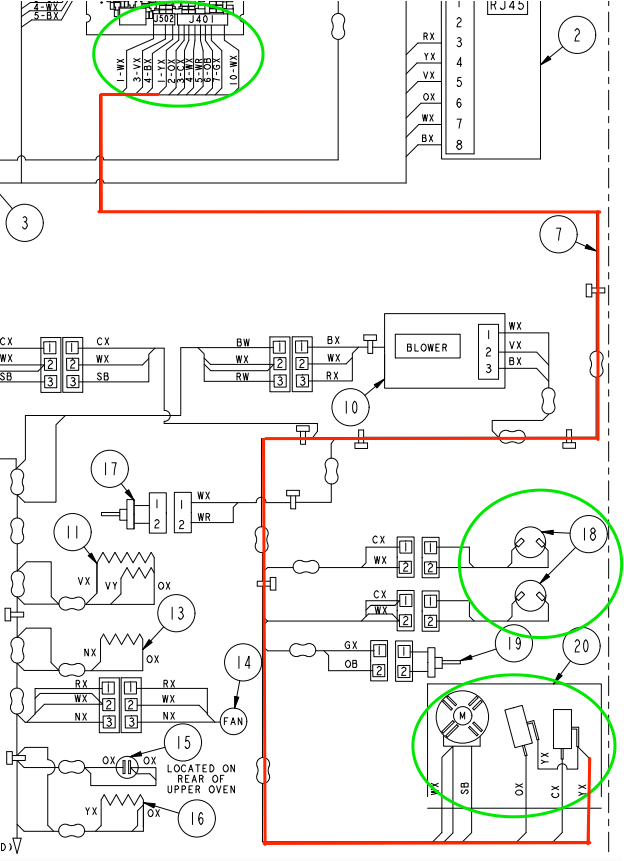
To follow any particular wire, you have to note its code and then follow the harness line to all its various terminuses until you see that wire code reappear. A bit tedious, but doable. For example, if we're interested in following wire YX, then we could trace it like so:
How Do We Use this to Troubleshoot?
We know that the wires going to the lights weren't broken -- the lights are on all the time. So the break must in another wire in this harness, and we know that the pinch was along the way to the door lock assembly.
What about those switches in the door lock assembly? Come to think of it, we didn't see those anywhere in the original schematic we looked at. What is the function of those switches, and what might happen if one of their circuits was broken?
To find our answers, we have to look at yet another part of the tech sheet. For whatever reason, GE's draftsmen decided not to give us all the information about this wall oven on one schematic. They have the ladder diagram that we looked at above, and then there's a separate control board schematic with other info. And on that diagram is the final piece of the puzzle...
Another Schematic from the Tech Sheet
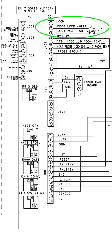
The circuits circled on the right are exactly those switches we were looking at on the wiring diagram. We now see their functions: one switch is the door lock switch, and the other is the door position switch. These switches give the board information about the state of the door and the door lock. The door lock switch tells the board if the lock is activated or not, and the door position switch tells the board whether the oven door is open.
Switches and Sensing Lines
Notice that the wires from these switches are connected to the DC side of the computer board, not to the loads (door lock motor and oven lights). Used this way, the switches make what's called sensing lines that the board uses for information, not power control. Sensing lines are used all over appliances and it's good to recognize them when you see them. When the oven door is closed, the door position switch is also closed (meaning it completes the circuit). Conversely, if the door position switch is open, the board interprets this as meaning that the oven door is open. The board senses the state of these switches (open or closed) and then makes software decisions about which loads to activate.
We now have Enough Information to Know Exactly What Happened!
When the wire harness got pinched, it broke a wire in the door position switch circuit. The board would see this as the door position switch being open. Based on this faulty information, the board does what it always does when it thinks door is open: it turns on the oven light and doesn't allow the door lock to be activated.
Our problem turned out to be a pretty simple one, but we had to bounce nimbly between three different diagrams as part of the troubleshoot. Only with info from the entire document could we arrive at the solution.
Want to learn how to read schematics and form troubleshooting plans like a pro? Click here to check out the Core Appliance Repair Training course over at the Master Samurai Tech Academy and enroll today.
-
.png) 5
5
-
 1
1
-
 1
1
10 Comments
Recommended Comments