Untangle This Tricky Water Valve Problem with the Troubleshooting Ten-Step Tango
At ASTI 2025 in Orlando, FL, I had the honor of teaching a class on reading schematics and troubleshooting using Master Samurai Tech's patented Ten-Step Tango troubleshooting technique. During that class, we did diagnostic workshops on a number of different scenarios, all of which were taken from right here at Appliantology. For those of you who couldn't make it out for the convention, let's run through one of those scenarios here.
We'll be running through the steps of the Tango, but for those who aren't familiar, you can download the steps here.
Here's the setup: you're working on an LG refrigerator, and the customer says that they're not getting water out of the dispenser. They also say that they can get ice out of the dispenser just fine.
Before we even head out on the job, we're going to start the Tango. In fact, the first seven of the ten steps can be done during prediagnosis. The very first step is...
1. Formulate the basic problem statement
This is where we take the customer's complaint, and we boil it down into a short, simple statement that answers two questions: what is the appliance doing that it shouldn't be doing? and what is the appliance not doing that it should be doing?
In this case, our problem statement would be not dispensing water. Simple enough.
2. Do a schematic overview
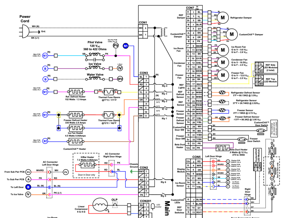
We head over to Appliantology, look up the tech docs for our model number, and we take a look at the schematic:
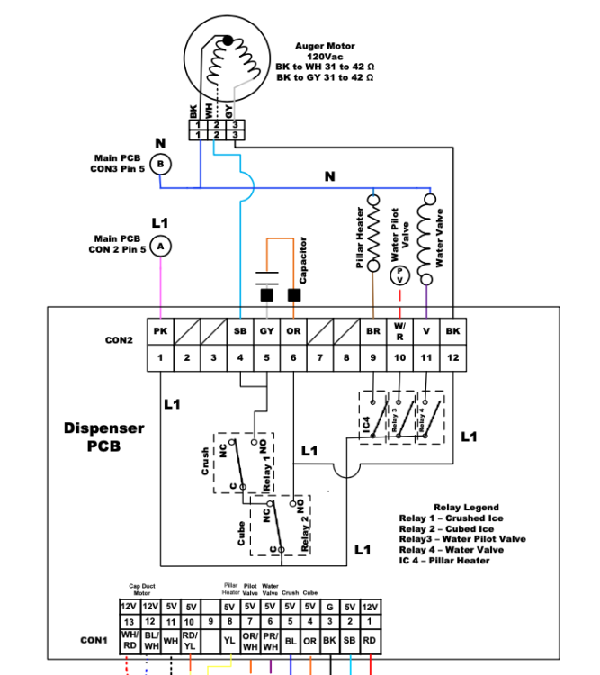
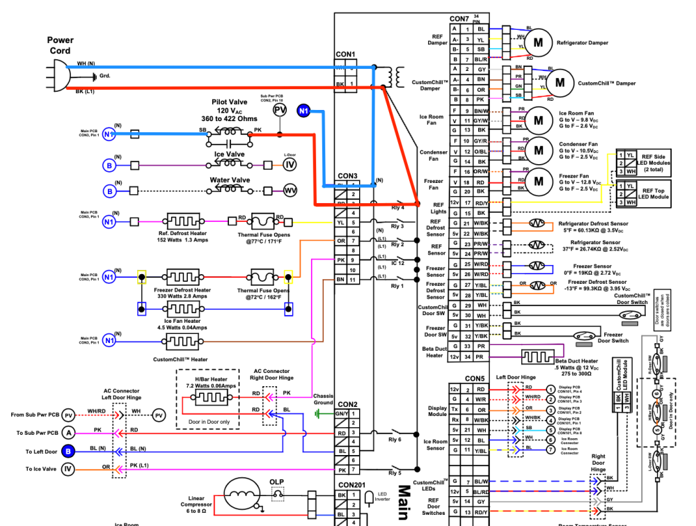
In this case, there's also a secondary schematic that we should take note of:
Now that we've got the schematics, next step...
3. Identify the Load of Interest (LOI)
The Load of Interest is, as we like to say, the thing that ain't doing its thang. It is not necessarily the load we think is the ultimate culprit -- we're not ready to make guesses yet. We're just identifying the load that is not behaving how it's supposed to as a starting point for our troubleshooting.
In our case, we could actually pick two possible loads of interest: the pilot valve or the water valve, since both need to open in order for water to flow from the dispenser. In cases like this, we can just pick whichever one we like to proceed with our troubleshooting.
Since the customer reported that there's no issue with ice production, it's reasonable to assume that the pilot valve works, since it needs to open in order for the ice maker to fill. So how about we pick the water valve as our LOI, since that's the valve specifically for water dispensing.
4. LOI Circuit Analysis
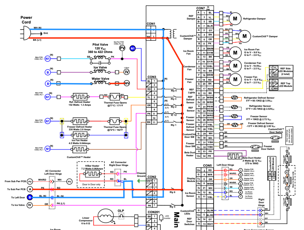
Now that we've picked the water valve as our LOI, we want to figure out how it gets its power supply. Since it's a 120 VAC load, that means we want to see how it gets line, and how it gets neutral.
When we trace it out on the schematic, it looks like this:
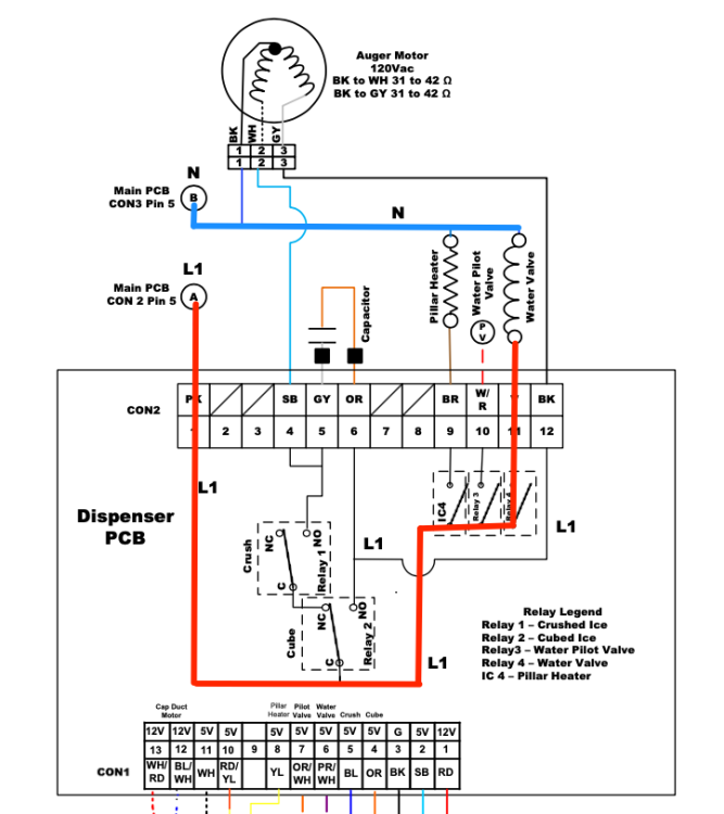
But that's not the whole story until we look at the dispenser PCB schematic, too:
Despite having to use two schematics to look at the water valve's full circuit, the circuit turns out to be pretty simple. Line and neutral both go through the main board, then through a wire harness. Neutral goes directly from there to the water valve, whereas line goes through a switch on the dispenser PCB.
5. Formulate a troubleshooting hypothesis
Now we're finally at the step where we make our hypothesis, which is our best educated guess at the cause of the problem statement, drawing on the analysis we've already done of the relevant circuits and our understanding of the technology. This guess needs to be something that we can perform tests to either prove or disprove.
A reasonable hypothesis would be failed water valve. Very straightforward -- if the water valve has failed such that it can't open, that would prevent the water dispenser from functioning.
6. Identify electrical measurements
Now that we have our best guess, it's time to see if it holds water. What kind of test would give us the most information for the least hassle?
After briefly pondering and scratching ourselves, we can conclude that a voltage test would be the easiest useful test. If we can determine whether the water valve is getting a valid voltage supply while the dispenser is activated, this will let us know if the problem is the valve itself or something else entirely.
We will of course use the LoZ setting of our multimeter for this AC voltage test, since we're techs who know our stuff.
7. Identify EEPs at which to make electrical measurements
We don't have to go at this like a caveman, tearing things apart until we get right to the component in question. Instead, we can find test points that are easier to access and electrically identical to performing the voltage test right at the valve.
For the first of our two test points, we can put a lead on CON2-11 on the dispenser PCB. That's where we should have 120 VAC when the dispenser is activated.
For our measurement's reference, we can use any easily accessible, unswitched neutral. You would normally want to use a neutral that's in your load's circuit to verify you have a valid neutral, but in our case, the water valve shares a neutral with the ice valve, and we know that the ice valve works fine and therefore has a good neutral.
8. Perform electrical measurements
Everything you have already done can be done before you're even on the job. We've only just now reached the step where you do need to be physically around the appliance.
Using the test points we already selected, we set up our meter leads and call for water at the dispenser.
The result: 120 VAC. Also, you hear the water valve hum when activated.
These findings by themselves are inconclusive. We need to do one more test to either prove or disprove our hypothesis: we should cheat the pilot valve. That means hooking the valve up to a cheater cord plugged right into a wall outlet.
But wait, why cheat the pilot valve? What does that get us?
Well, we know that the water valve has a good power supply, and we know from the fact that it's humming that it's at least trying to open. We have not yet checked the pilot valve's power supply, so we don't know anything about its current state. If we cheat the pilot valve and then activate the dispenser, whether we get water or not tells us with 100% certainty if the water valve is bad.
And as it turns out, when we do the test like this, we get water happily shooting out of the dispenser.
9. Compare the electrical measurements with expected readings or specifications
So where does that leave us? Well, we have successfully disproven our hypothesis. If the water valve had failed, then we would not have gotten any water out of the dispenser when we cheated the pilot valve and activated the dispenser.
While we're not at the end of the road yet, disproving a hypothesis is a good thing! It means we're zeroing in on the solution.
With all the information we've gained from our tests, we can go back to step 5 of the Tango and form a new, more informed hypothesis.
Step 5 revisited: new hypothesis
It's time to sit with our findings in deep and tranquil meditation so that we can make a new hypothesis. We know that both the water and pilot valves are good. They are fully capable of opening. And we know that the water valve's power supply is in perfect working order, so the water valve is completely cleared of any suspicion.
Our new LOI becomes the pilot valve.
At first, the idea that there's anything wrong with the pilot valve's circuit seems a bit confusing. We know that it runs just fine when the ice maker calls for a fill. So how can there be an issue with its power supply?
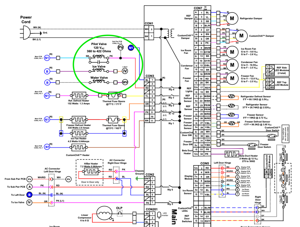
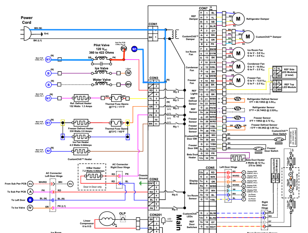
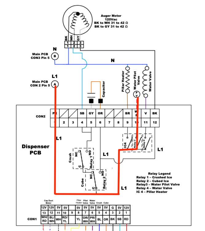
Well, if we study the schematic some more, we can see that there are actually two different ways for the pilot valve to get its line voltage supply.
It can get its voltage supply through the main board, as shown here:
Or through the dispenser PCB, as shown here:
And now it starts to come together.
Our new hypothesis is: missing line voltage to the pilot valve during water dispensing
Following the Tango again, we can quickly make a voltage measurement at CON2-10 on the dispenser PCB while activating the dispenser. Surely it must be something like a failed switch on the dispenser PCB, right? Surely we won't find our voltage supply.
But we do -- we have a solid 120 VAC at CON2-10.
This doesn't disprove our hypothesis, though -- we need to see now if this voltage is actually making it to the pilot valve.
So we go directly to the pilot valve, place our probes, activate the dispenser, and...
Nothing. 0 VAC.
Finally, after our long odyssey, we have found the cause of our issue. There is a break in the wire harness somewhere between the dispenser PCB and the water valve. We can even do a continuity test of the wire to confirm this.
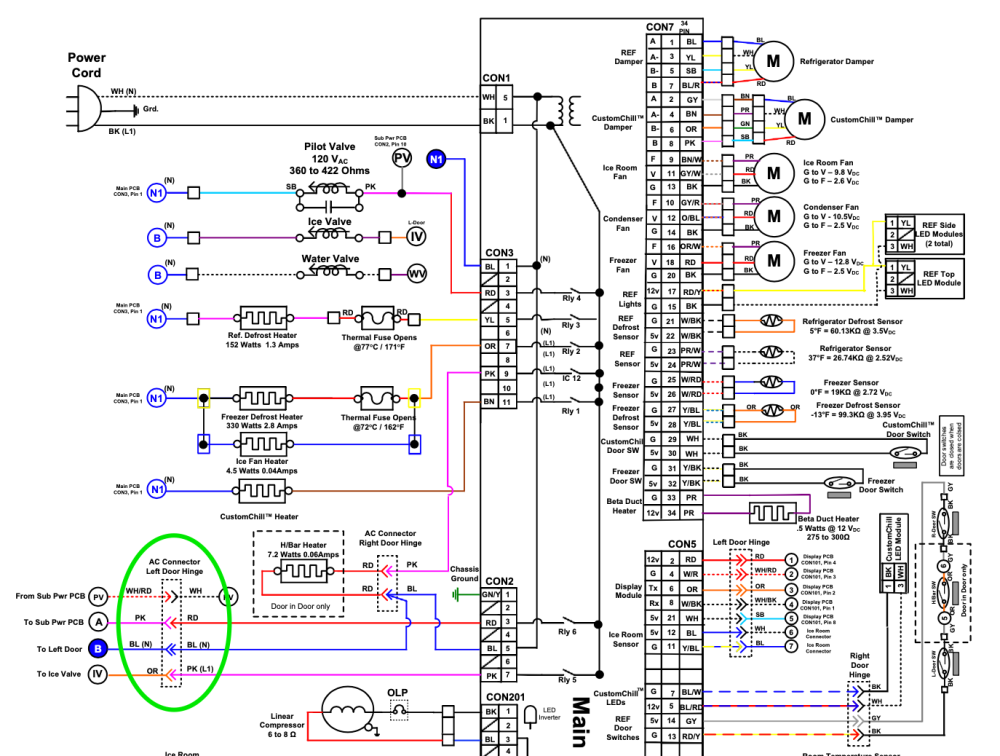
Looking at the schematic once more, we can form a good idea of where to look first for our broken wire:
Harness connectors through door hinges can be notoriously prone to breaking. And lo and behold, when we inspect the wires in that harness, we find a break in the wire, as expected.
And so, we can move onto the final, coveted step of the Tango...
10. Make the repair and check for proper operation
With the new wiring installed, all that you need to do is put a cup in the dispenser to make sure everything is working as it should.
And there you have it --another tricky issue untangled with the help of the patented Ten-Step Tango.
Did you get lost anywhere along the way? Do you want to learn more about the Tango and how to apply it to any tricky scenario you encounter? Check out the Core Appliance Repair Training course over at the Master Samurai Tech Academy.
-
.png) 10
10


7 Comments
Recommended Comments