
Loading Meter Resurrects a Dead Dryer

Entry posted by Son of Samurai in Tech Talk
549 views
An interesting topic came up here in the Appliantology forums a little while back:
The tech was working on an electric dryer that was DOA -- no lights, no response to button presses. He put his multimeter to the LoZ setting (as you should always do when making AC voltage measurements!), and he started checking for the power supply to the appliance at the terminal block. Here's what he got:
L1 to N: 0 VAC
L2 to N: 120 VAC
L1 to L2: 20 VAC -- and while the meter leads are held on L1 and L2, the dryer UI lights up!
Huh? What's going on here, both with the strange voltage reading from L1 to L2, and with the dryer coming to life while that voltage measurement is being taken?
Let's crack out the schematic and find out. Here's the dryer schematic with the power supply to the board marked up.
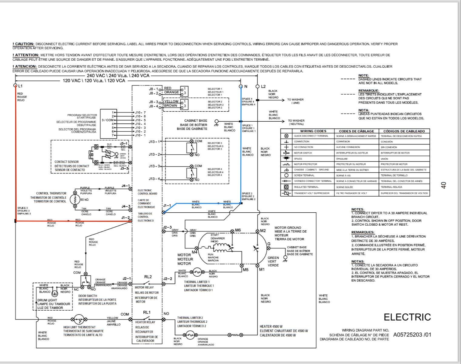
As you can see, the board's power supply is L1 and Neutral. There's no switch in either Line or Neutral going to the board -- the board is hardwired to its power supply. That, combined with the fact that, even when we measure at the terminal block, we get 0 VAC from L1 to Neutral, seems to indicate that we're missing L1, probably due to an open in the wall outlet or the house wiring.
But how then is the board coming to life during our L1 to L2 voltage measurement? Well, let's look at what we're doing on the schematic when we perform that voltage measurement.
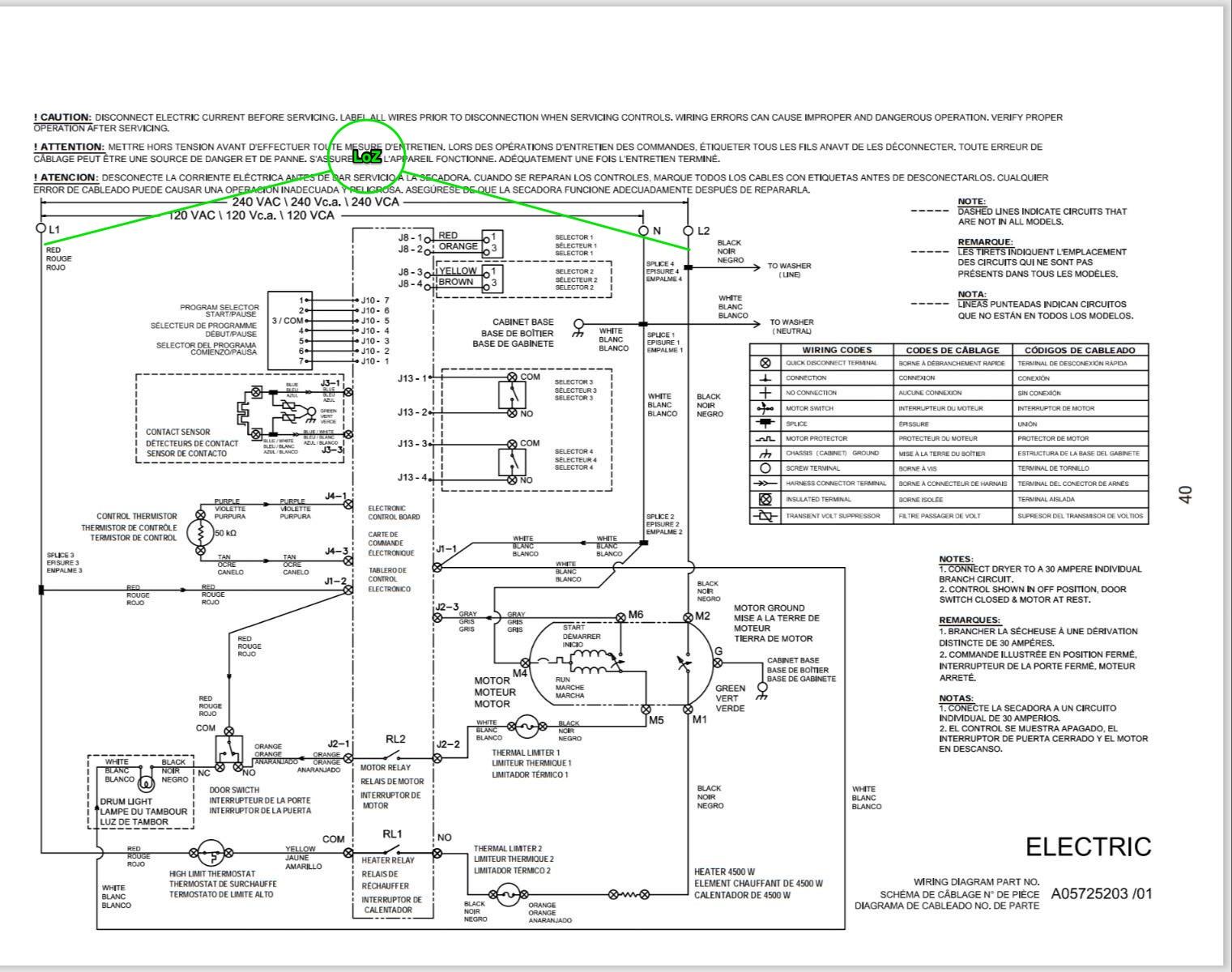
How does connecting the meter like this cause the board to come to life? It's because we are connecting L2 to the L1 side of the circuit through the loading meter. Here's a simplified drawing of what's happening:
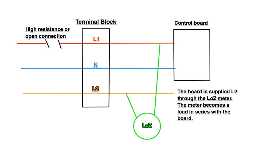
We are effectively creating a series circuit with the loading meter and the control board. This also explains the weird voltage reading we got measuring from L1 to L2 -- that's how much voltage was being dropped across the loading meter.
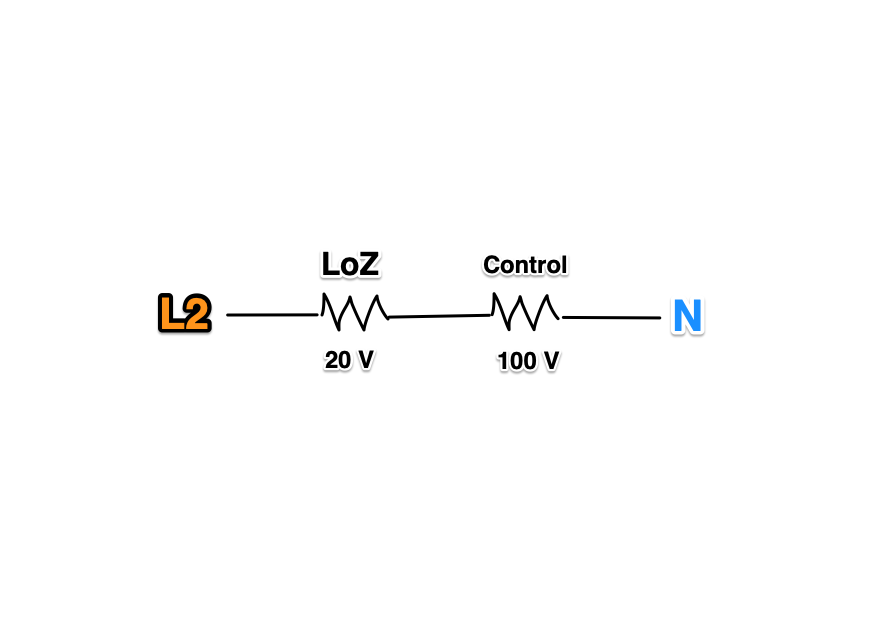
This is what that circuit looks like, drawn out as a line diagram.
So there you have it -- a weird problem with whacky symptoms that turns out to have a simple solution! All of this came from a missing L1 at the wall outlet, the kind of thing you can easily catch by taking a measurement right at the outlet with a loading meter.
Want to get in on the action? Join the Brotherhood of Techs at Appliantology.
- Appliantology.org is a cultivated, private community of techs.
- Get solid tech advice from working, professional techs and business owners.
- Avoid the endless noise and guesswork thrown at you from groups on social media.
- Download the service manuals, tech sheets, and service bulletins you need to git 'er done.
Join the Brethren in the Craft right now with our membership options at Appliantology and see how it can help you in your business starting today.
-
.png) 5
5


1 Comment
Recommended Comments