Jump to content
Click here to take a sample course.

FAQs | Repair Videos | Academy | Newsletter | Contact


Appliance Repair Tech Tips

  • entries
    257
  • comments
    839
  • views
    558,156

Pop Quiz: Are These Loads in Series or Parallel?


Are the dispenser heater and fill tube heater in series or parallel? Or perhaps they're neither?

IMG_3168.jpeg.8752c15638cdef380c352b84c588ef27.jpeg

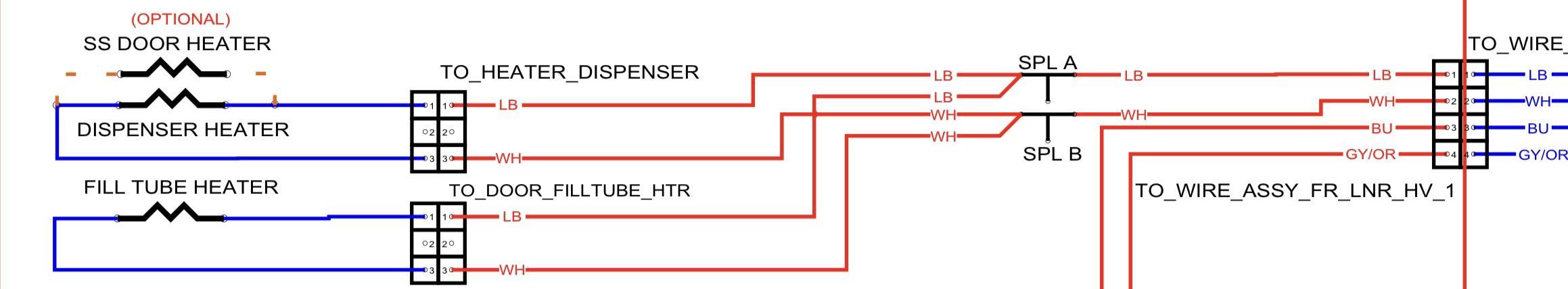
BONUS QUESTION: If both heaters have 6.3 kohms of resistance, roughly what resistance would you expect to read from pin 1 to pin 2 of the connector?

Sound off in the comments!

  • Like 1

6 Comments


Recommended Comments

MAKEITINAPPL

Posted (edited)

I am assuming SPL A and SPL B, stand for splice A and B, then I have to say they are in series, because both heaters have the same voltage source and the same return path to Neutral. I may be wrong though. Total R should be 12.6K ohms.

Edited by MAKEITINAPPL
  • Team Samurai
Son of Samurai

Posted

5 hours ago, MAKEITINAPPL said:

I am assuming SPL A and SPL B, stand for splice A and B, then I have to say they are in series, because both heaters have the same voltage source and the same return path to Neutral. I may be wrong though. Total R should be 12.6K ohms.

Good observation on the splices!

If the heaters have the same voltage source and same path to Neutral, does this mean that they are in series or parallel?

MAKEITINAPPL

Posted (edited)

2 hours ago, Son of Samurai said:

If the heaters have the same voltage source and same path to Neutral, does this mean that they are in series or parallel

On second thought, if each load can reach directly to the Voltage source and to Neutral independently of the other load then they must be in parallel.

Edited by MAKEITINAPPL
  • Like 2
Slav

Posted

If you redraw those splices, it becomes easier to see that they are in a parallel circuit. That means the total resistance should be about half the smallest resistor (without using the formula🤪). Since they are both 6.3 kohms, I'd say the total should be about 3 kohms.

image.thumb.png.71a9867865bf94c6cb6d3c3e7f6ac766.png

  • Like 3
JohnC

Posted

I’m seeing a parallel circuit with a total resistance of 3,150 ohms.


Slav’s drawing helps visualize it.

  • Like 1
  • Team Samurai
Son of Samurai

Posted

On 8/27/2025 at 2:19 AM, Slav said:

If you redraw those splices, it becomes easier to see that they are in a parallel circuit. That means the total resistance should be about half the smallest resistor (without using the formula🤪). Since they are both 6.3 kohms, I'd say the total should be about 3 kohms.

image.thumb.png.71a9867865bf94c6cb6d3c3e7f6ac766.png

Great sketch, Slav, and you're spot on! It's a parallel circuit, and the equivalent resistance would be something in the neighborhood of 3 kohms.

When you have two loads in parallel, the rule of thumb is that the equivalent resistance of those loads (in other words, what your meter will read when measuring the resistance of the entire circuit) is a little less than half the resistance of the lowest resistance load.

×
×
  • Create New...