Had some good questions at the webinar on the Bi-Directional PSC drive motor system used in Whirlpool VM washers. Professional Appliantologist members can grab some popcorn and watch the webinar recording here: Bi-directional PSC Drive Motor Systems in Whirlpool VM Washers
During the webinar, Joe asked how triacs are turned off. I wanted to give a more complete and accurate answer in this post.
To understand how triacs are turned off once they're turned on (and conducting) we need to have a little understanding about how triacs work. So that's what I'm going to do here. Before we light this candle, I'll start with the three take-away points that we need to know about triacs:
1. Triacs are used to control AC power supplies
2. You can think of them as solid state relays
3. Triacs are current controlled devices. This means that you need electrons bustin' down the Gate to turn it on AND you need load current flowing through them in order to stay on.
Okay, here we go...
Intro
The word "Triac" is an acronym that stands for Triode for Alternating Current. "Triode" is the old Skool word for a three-terminal (or electrode) vacuum tube used to amplify a signal.
Triacs are used to control a AC power supply. In appliances, they are used to turn the AC power supply off or on.
Here's what a typical triac looks like, such as what you might find on an appliance control board:
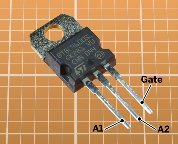
Here is the schematic symbol:

The leads labelled A1 and A2 stand for “Anode 1” and “Anode 2.” You will also see them referred to as “MT1” and “MT2” where MT stands for Main Terminal. Same thing. This is the business end of the triac where the main working current passes. This part of triac can complete the circuit for lots of different AC loads, from light bulbs to motors.
The other important thing to point out is the “G” terminal. This is the Gate and it has the power to turn the triac on with just a little DC voltage, usually a 5 VDC digital pulse generated by a microprocessor. So this little Gate voltage and tiny current can make a triac turn on and pass a heap big mondo working current.
Triacs are like solid state relays and, in the appliance world anyway, serve the purpose of the relays with a coil and set of contacts. The difference is that triacs don't have metal contacts that can arc and burn out and don't have a coil. (And, of course, triacs are made of semiconductors and PN junctions. More on that in a bit.)
Relays are electromechanical devices whereas triacs are solid state devices.
Inside a Triac
Triacs have two sets of three PN junctions. Look at the diagram below:
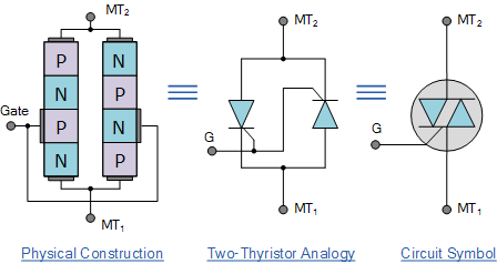
As with any semiconductor device, it requires current flowing through it, or more properly stated, electrons being forced through it by a voltage source, in order to collapse the PN junctions and cause it to start conducting. Refer to the webinar recording on “Semiconductors and PN Junctions” in the Professional Appliantologists forum and at Master Samurai Tech for more details on this.
The triac is constructed in such a way that a little tiny gate current is all that's needed to “forward bias” the triac and make it turn on and conduct a large AC current that can drive a load like a motor. This Gate current is typically driven by a small DC voltage like 5VDC.
Turning a Triac On and Off
Triacs require a minimum current through the Gate in order to turn on. In order to stay on, they also need a minimum load current flowing through them from MT1 to MT2. This is called the “holding current.” This is why we say that triacs are current controlled devices.
When the AC voltage crosses the zero line (the x-axis), the current then goes to zero and the triac “turns off.” So the triac naturally turns off at every half cycle of the AC sine wave. The Gate voltage, which produces the Gate current, must then be reapplied in order to the turn the triac on for the next half cycle.
Let's look at this:
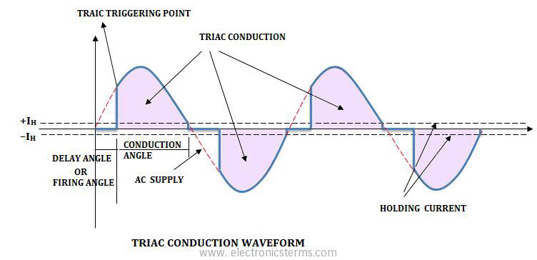
In the diagram above, the sine wave is the current passing through the triac from MT1 to MT2 (or A1 to A2, same thing). The notches represent the triggering points where Gate current has to be supplied in order to keep the triac turned on for the next half cycle. Also notice the holding current dashed lines. This is the minimum current that needs to be passing through the triac in order to stay on.
AC voltage goes to zero every half cycle (60 times a second in a 120 Hz power supply). No voltage means there's no current because current, electrons, cannot move unless there is a voltage difference between two points as you learned in the Basic Electricity module of the Fundamentals course.
Since there is no current flowing through the triac at this point forcing the PN junctions to stay collapsed (current drops below the minimum holding current required to keep the triac conducting), the triac turns off and stops conducting.
To get the triac to turn on and start conducting again, you have apply a Gate trigger voltage (which drives the gate current) to the Gate terminal. If you to want to have the triac conduct through several AC cycles, you have to re-apply the Gate trigger voltage each and every time the AC voltage sine wave goes to zero (i.e., when it crosses the x-axis).
Here's another diagram showing the gate current triggering pulses:
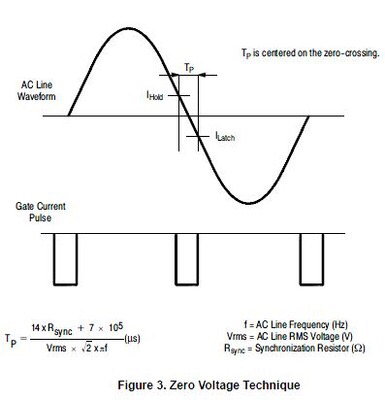
A couple things to notice about the graph above:
1. Look at the timing of the Gate current pulse. It occurs right around the time the AC load current through the triac goes to zero.
2. You don't need to keep supplying Gate current the entire cycle to keep the triac turned on, just when the load current goes to zero. So you can supply Gate current in specifically-timed pulses. We're talking accurate timing down to the microsecond. Mind boggling for us; piece of cake for a microprocessor-- they do this kind of stuff all day long.
If you were to connect an oscilloscope to both the gate voltage and the voltage output at one of the the triac main terminals, it would look something like this:
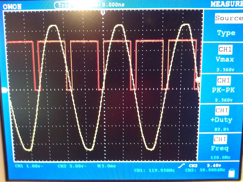
The Gate pulses in the oscilloscope photo above are wider than the ones in the preceding diagram but the idea is exactly the same. Channel 1 is the Gate voltage and Channel 2 is the AC voltage output of the triac.
I'm talking about voltage now. That's perfectly fine because in non-reactive devices, like triacs, there is no phase shift between current and voltage. So whatever voltage does, current also does at the exact same time. It's just easier to show voltage on an oscilloscope.
Notice that the gate pulse on Channel 1 goes from zero to 5.5 VDC each and every time the AC voltage sine wave on Channel 2 crosses the x-axis (at which point the AC voltage is zero). So while the frequency of the AC line voltage is 60 Hz, the frequency of the Gate pulses is 120 Hz. You can see this in the lower right hand corner of the photo above.
Since the AC voltage (and hence current) goes to zero 120 times a second, all you need to do to stop the triac from conducting is remove the Gate voltage. Done!
The Two Golden Rules for Gating Triacs
1. To turn a triac ON, a gate current greater than the minimum required for that particular triac model must be applied until the load current is passing through from MT1 to MT2 . Being a semiconductor, temperature affects this and is one of the design considerations the engineers have to consider.
2. To turn off a triac, the load current must go below the minimum holding current for that particular triac model long enough for the PN junctions to re-establish themselves. We're talking microseconds here. And, of course, remove the Gate current. With the Gate current removed when the load current (and hence voltage) goes to zero, the triac will not conduct, even if the load voltage later goes to something other than zero.
Summary
1. Triacs are used to control AC power supplies
2. You can think of them as solid state relays
3. Triacs are current controlled devices. This means that you need electrons bustin' down the Gate to turn it on AND you need load current flowing through them in order to stay on.
Beyond understanding how triacs operate, technicians need to be aware of configurations where a triac is controlling the power supply to a load because this affects how the supply voltage is tested and measured. We go into details on that in this webinar recording: Voltage Measurements, Meters, Ghost Voltages, and Triac-controlled Neutrals
-
.png) 3
3
-
 3
3

.png.aa21533c6656a1cb054a172848652cb2.png)


9 Comments
Recommended Comments