
BLDC Motor Configurations, FG signals, and PWM signals

Entry posted by Son of Samurai in Tech Talk
15,556 views
BLDC motors aren't new technology in appliances anymore -- in fact, they've become the norm. As such, it's important to be aware of the different configurations you'll see these motors in across appliances. These configurations fall into three categories: 2-wire, 3-wire, and 4-wire.
An important thing to note before we continue: all BLDC motors in appliances are run by inverters. The inverter may be a separate board, like you'll see in washers with BLDC motors, or it may be built into the motor itself, which is what you see with smaller ones like fan motors.
For our first configuration: 2-wires. This is as simple as it gets -- you just have DC voltage on one line, and DC ground on the other. These motors will run at one speed and one speed only when it receives power. Nothing fancy here.
3-wires is where it gets interesting. Here's an example of some 3-wire BLDC fan motors in a refrigerator schematic:
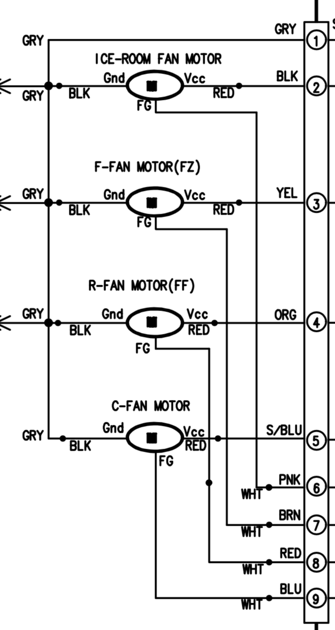
Naturally, two of those wires are still your DC voltage and DC ground. But what's that third one doing -- the one marked as FG in this diagram?
That line carries the FG (Frequency Generator) signal. That's a feedback signal consisting of a series of voltage pulses at regular intervals that the motor sends to the control board. This isn't something that the motor just does by itself -- it has to be fitted with a sensor (usually a hall sensor) that can generate this signal every time the motor completes a revolution. The control counts these pulses, then calculates based on that how quickly the motor is turning.
That's probably the most common 3-wire configuration you'll run into, but it's not the only possible one. Instead of being a feedback line, that third wire could be for carrying a PWM (Pulse Width Modulated) signal from the main control to the inverter. See here:
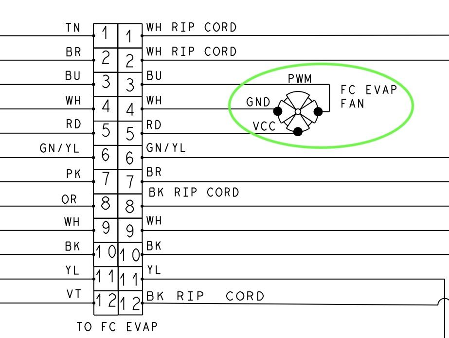
This signal is the control telling the inverter how quickly to run the motor. With a PWM signal, variable speeds become possible. However, in a 3-wire configuration with a PWM signal, the control wouldn't be able to detect how quickly the motor is running --- just as the control couldn't vary the speed of a 3-wire motor that has an FG signal wire.
To determine which variant of the 3-wire configuration you have, the tech doc usually has to tell you. For example, we know that we have an FG signal setup on that first diagram because the third wire is labelled as such.
Last but not least is the 4-wire configuration. This has the best of both 3-wire variants. Two of the wires are, again, your DC voltage and DC ground. Of the other two, one will be your PWM signal from the control to the inverter, and the other will be your FG signal from the motor to the control. This way, the control can both vary the speed of the component and monitor its rotation.
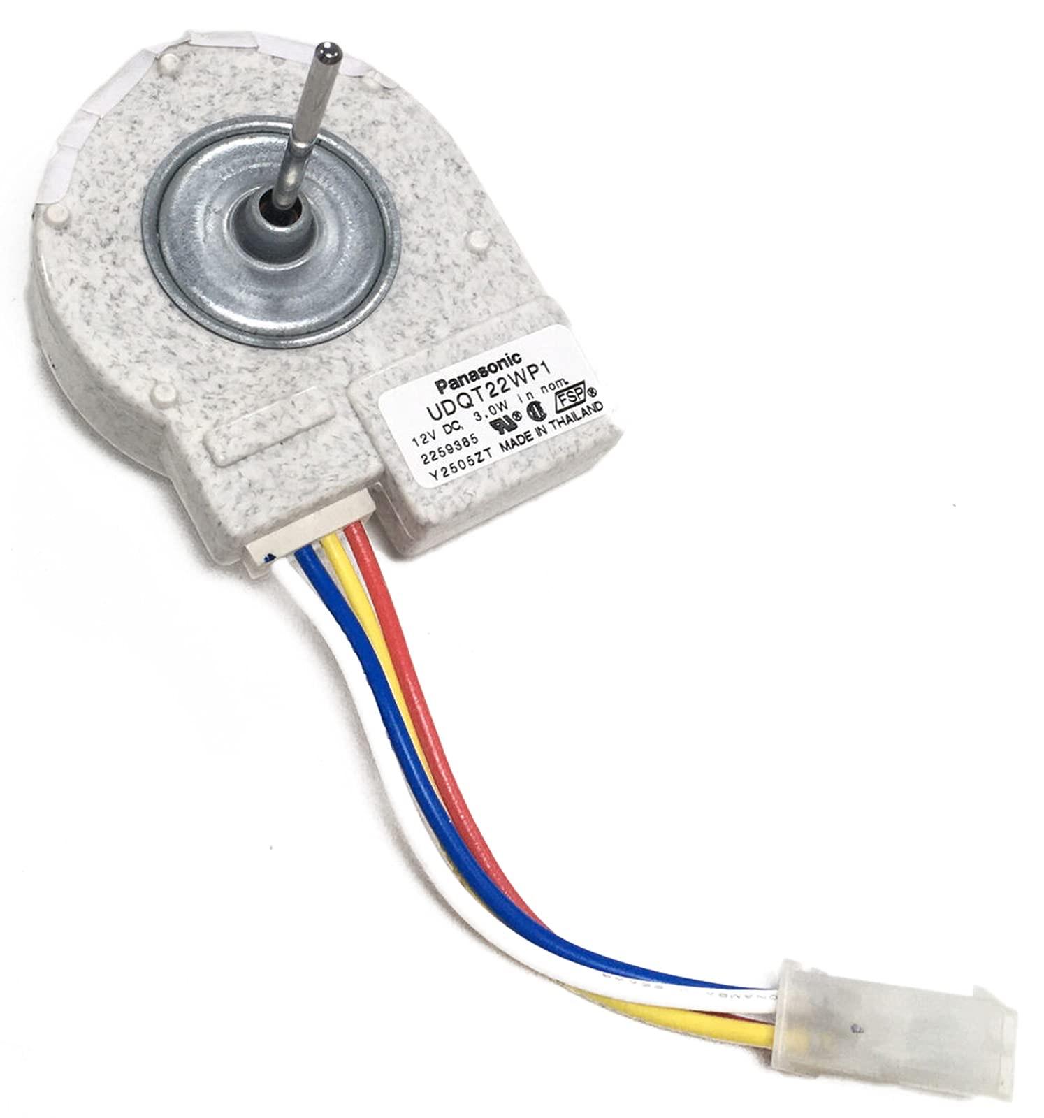
Here's an example of what one of these low-voltage, 4-wire BLDC motors looks like:
Now, you might have a question: how can I tell which wire is which? Do I just have to rely on the tech sheet to tell me?
Not necessarily! There is actually a wire color convention for these kinds of motors. It's not universal, but if you see the specific combination of red, white, yellow, and blue wires, then you know what's on each wire.
- Red: DC voltage
- White: DC Ground
- Yellow: FG signal
- Blue: PWM signal
This wire color convention can sometimes help you with 3-wire configurations, too:
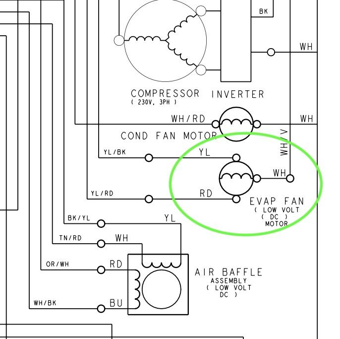
In this one, we can tell from the wire colors that the yellow wire is an FG signal.
Want to step your tech game up to the next level? Click here to enroll today in the Core Appliance Repair Training course at the Master Samurai Tech Academy.
-
.png) 12
12
-
 5
5


4 Comments
Recommended Comments