Can you Measure the Output of an Inverter?
When it comes to troubleshooting BLDC motors and inverters, there's usually a standard strategy. You check the input to the inverter (a good 120 VAC power supply and a PWM signal from the main control) and you make sure the motor windings are in spec and all the same resistance. But what about measuring the output of the inverter?
This is certainly possible to do, and it can be a useful measurement, especially in hairier inverter troubleshooting scenarios. But before we get into that, let's make sure we're all on the same page when it comes to inverter technology.
While BLDC motors may be called DC motors, they actually run on electronically commutated AC power. The image below shows what I'm talking about.
This is showing a simplified diagram of what the inverter is doing many, many times a second. It sends direct current through one set of motor windings, then uses its electronic switches to swap windings, and so on around and around. In this way, it is creating three-phase AC power. And since this is AC voltage, we can measure it with a standard digital multimeter.
There are two main factors we're concerned with: voltage and frequency. Voltage can be measured simply using your normal AC voltage setting. Frequency can be measured with -- you guessed it -- the frequency setting. Most DMMs have this.
There are a few complications that have to be accounted for when testing an inverter in this way.
First, physically accessing the harness can be difficult. These tests must be made while the inverter is connected to the motor. The inverter and motor are oftentimes not placed in the easiest to access place, so you may need to either perform some contortionism or create a clever rig.
Second, since this is three-phase power that we're measuring, you need to measure phase-to-phase. The way you do that is by simply measuring each of the three power output terminals with respect to the others. So if you have terminals labelled 1, 2, and 3, you would measure from 1 to 2, from 1 to 3, and from 2 to 3.
The third and most important complication is that there is no standard spec for the voltage and frequency, and manufacturers are often not very good about giving you a spec in their documentation. This means that this test, while useful, can often only be a qualitative test. It gives you a feel for if things are working correctly without providing a hard data point.
So without a spec, what are you looking for? Primarily, you're looking for stability. Any kind of erratic voltage or frequency measurement should raise a red flag. And, of course, if one of these measurements comes up blank or extremely low, that's an obvious issue.
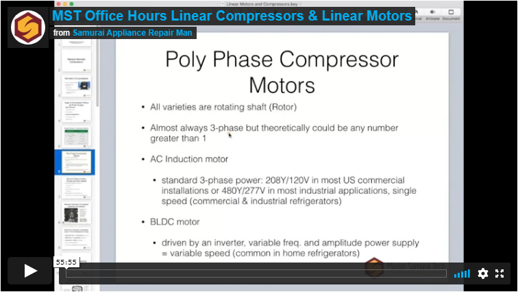
Want to learn more about troubleshooting motors, both BLDC and linear? Check out this excerpt from our webinar recording that dives into that.
Want to watch the full webinar recording? Click below -- viewable only by premium members.
-
.png) 3
3

.png.aa21533c6656a1cb054a172848652cb2.png)


1 Comment
Recommended Comments