Jump to content
Click here to check out our on-demand appliance repair training webinars.

FAQs | Repair Videos | Academy | Newsletter | Contact


Appliance Repair Tech Tips

  • entries
    224
  • comments
    762
  • views
    523,892

How Do the High-Voltage Circuit and Magnetron in a Microwave Work?


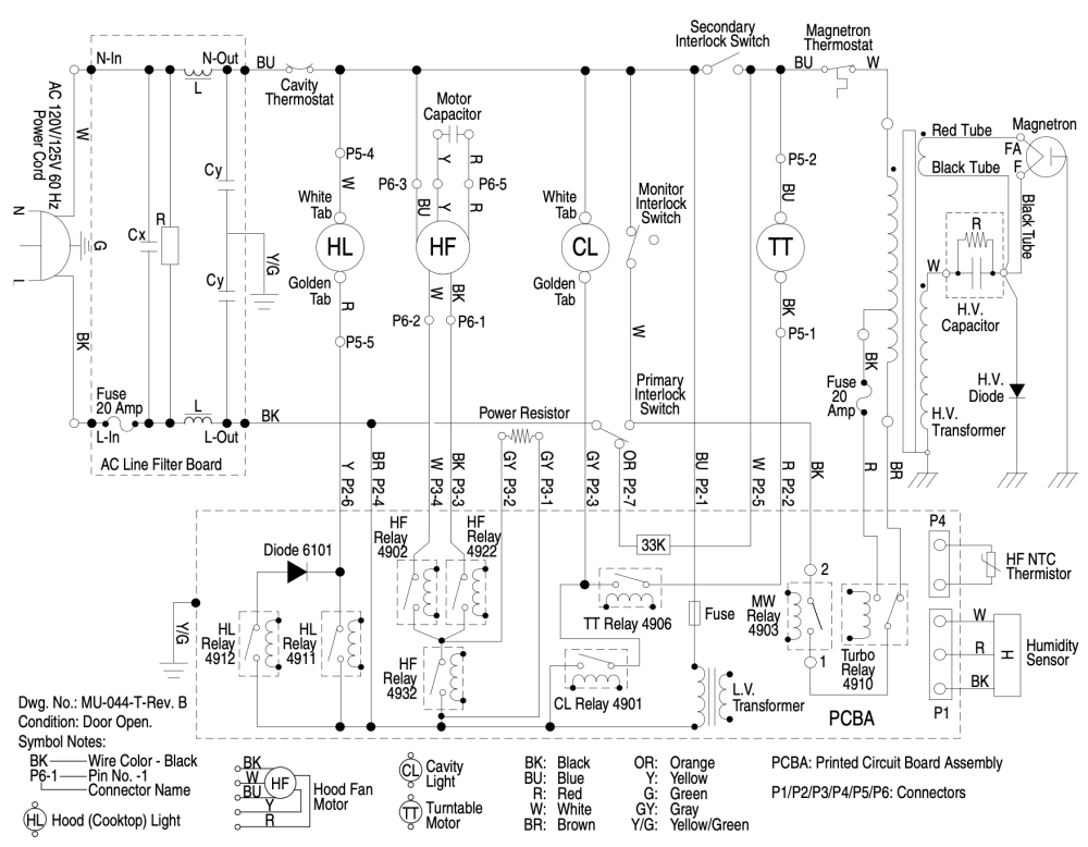
We're going to take a dive into what exactly is going on electrically with the high-voltage circuit in a microwave. We'll use this specific schematic as an example, but these principles apply generally.

Screenshot 2023-03-08 at 8.31.48 PM.png

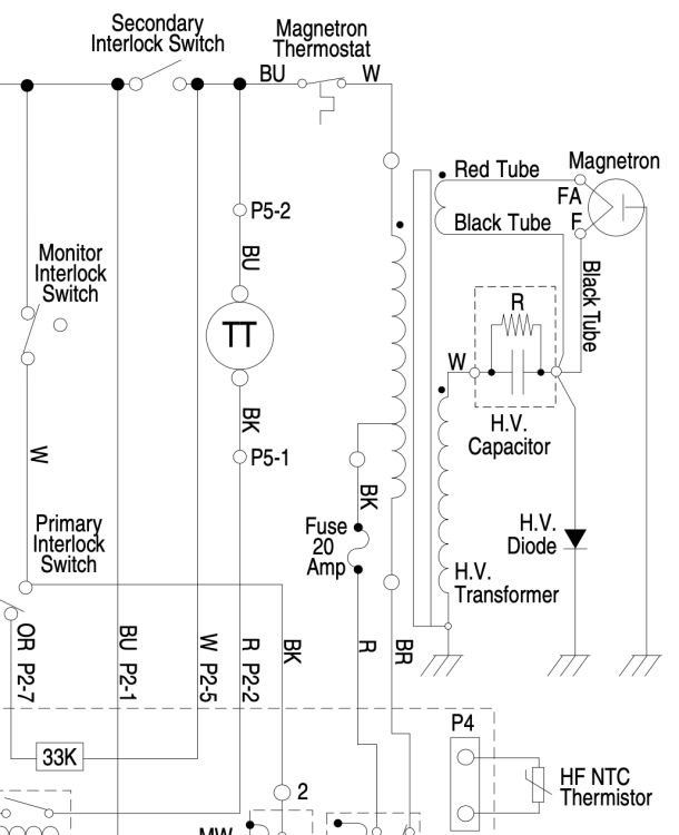
Don't worry about most of the schematic. All that matters to us right now is the high-voltage section -- the transformer on the right side of the schematic and everything to its right.

Screenshot 2023-03-08 at 8.34.00 PM.png

If you're not familiar with how magnetrons work (or even what they are), then this circuit probably doesn't make much sense to you. Why all the ground connections? What's the purpose of the capacitor and diode? What's with the two different secondary windings of the transformer?

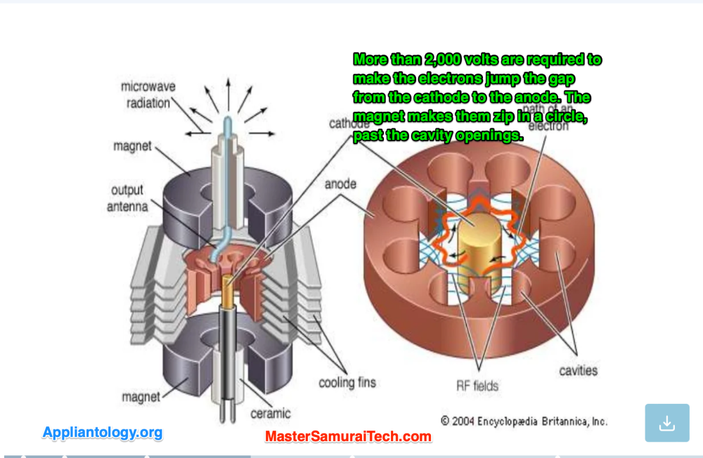
Let's start by taking a look at how a magnetron works. Here's a cross-section that shows you the guts of one of these things.

image.png


There's a lot of cool stuff that goes in with a magnetron, but we'll just focus on the basics.

The magnetron is the device that produces the microwave radiation that heats food within the appliance. This is done by applying a very high voltage to the cathode of the magnetron, usually around 4,000 volts. This voltage forces electrons to jump ship, arcing through the air (actually it's in vacuum) to the anode, which is the shell surrounding the cathode. The anode is fitted with cavities (seen above), and as electrons zip past these cavities, they produce microwaves. These microwaves are then guided into the food cavity of the appliance.

We're just skimming the surface here, but that's all we need to know as techs: when the magnetron is supplied with the proper voltage of 4,000 volts, it will perform its function. But 4,000 volts is a lot compared to the 120 volts that the appliance gets from the wall outlet. How do we get that? Well, that's exactly what all those components in the high-voltage circuit do.

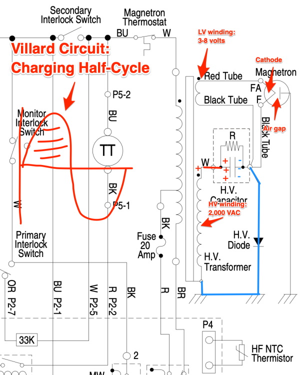
The first step is the transformer, which steps 120 VAC up to 2,000 volts. That's a huge increase, but it still only gets us half the way. We need to find a way to double that voltage -- and as it turns out, there is a handy circuit configuration for this called, predictably, a voltage doubler. There are a many different kinds of voltage doubler circuits, but this machine uses a pretty simple one called a Villard circuit. A Villard circuit doubles voltage in choppy pulses. This is because it requires one half of the AC power cycle to charge up, and then the other half to discharge.

Let's take a look at what we mean by that, one half-cycle at a time.

Screenshot_2023-03-08_at_8_34_00_PM.png

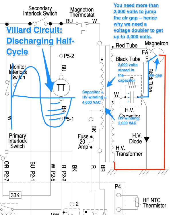
During this charging half-cycle, the magnetron is not producing any microwaves. Instead, electrons are being sucked up from ground, through the diode, and stored in the capacitor.

At this point, I can also explain what the point of the low-voltage winding and the "red tube" and "black tube" are. All that does is pass a tiny current through the cathode to keep the magnetron warm during this half-cycle. Those "tubes" are just standard wires. Why are they called tubes? Korenglish, baby.

So, at the end of this half-cycle, we have 2,000 volts stored in the capacitor, and we're ready to flip polarity. Let's see what happens then...

Screenshot_2023-03-08_at_8_34_00_PM-2.png

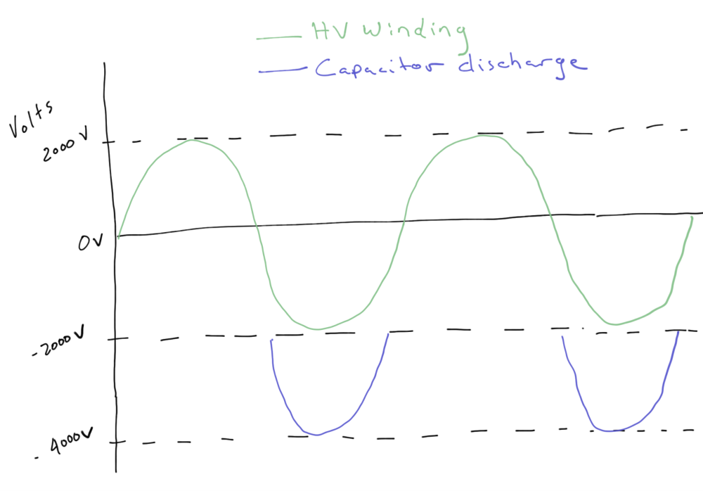
(Note: It's not really an air gap because the cathode and anode are inside a vacuum tube.) Here we see the Villard circuit do its thing: the 2,000 volts that we stored during the charging half-cycle add to the 2,000 volts on the high-voltage transformer secondary, producing 4,000 volts. Since the diode only allows current to flow one way (the way it was flowing during the charging half-cycle), current can't just flow directly back to ground. Instead, it's forced to jump the gap in the magnetron, producing all those microwaves.

Here's what the voltage sine wave looks like across multiple cycles:

Screenshot 2023-03-08 at 8.32.16 PM.png

After the electrons jump the gap in their quest for Ground, the magnets prevent them from taking a straight path and force them to whiz by the open resonant chambers. As they do this, they produce electromagnetic waves in the microwave spectrum. It actually works very much like when you blow through a whistle, except it's electrons moving past the cavities instead of air particles, and microwave radiation that gets produced instead of sound waves. This microwave radiation is then directed into the cooking cavity to warm the food.

Cool stuff, right? Want to learn more about the technologies common to all appliances, and how to apply that knowledge to real-world troubleshooting? Click here to check out the Core Appliance Repair Training Course over at the Master Samurai Tech Academy.


  • Like 9
  • Thanks 3

17 Comments


Recommended Comments

Coley

Posted

Great stuff!!

  • Like 1
FortRepairs

Posted (edited)

Any chance we could get into more detail on the science of how the HV Transformer takes the 120v to 4000v? Microwaves are easily the most fascinating appliance. 

My favourite thing is that you can use them to make plasma by microwaving a match under a glass.

Also small detail at the end of the article states the sound waves heat the food but the process of the electrons crossing the gap creates electromagnet radiations which isn't sound waves. 

Edited by FortRepairs
  • Team Samurai
Son of Samurai

Posted

53 minutes ago, FortRepairs said:

Any chance we could get into more detail on the science of how the HV Transformer takes the 120v to 4000v? Microwaves are easily the most fascinating appliance. 

My favourite thing is that you can use them to make plasma by microwaving a match under a glass.

Also small detail at the end of the article states the sound waves heat the food but the process of the electrons crossing the gap creates electromagnet radiations which isn't sound waves. 

You're correct on the bit about sound waves -- I was intending to simplify it by way of analogy, but it was too imprecise. I've made that section a bit more technically accurate.

As for the transformer (which only steps up to 2,000 VAC, by the way, not 4,000), that's a whole little world unto itself that goes a bit beyond the scope of this article. Probably a good topic for a whole separate blog post! But to put it very simply, transformers work based on how they're physically constructed -- specifically, the ratio of turns in the primary coil vs. the secondary coil. The more turns in the secondary compared to the primary, the higher the voltage gets stepped up.

  • Like 2
FortRepairs

Posted (edited)

The detail for the HV tranformer is definitely for the sake of curiosity. I found this page which does a great job and lays out the equations. Not useful for our work, but you get to feel smart. 

https://phys.libretexts.org/Bookshelves/College_Physics/Book%3A_College_Physics_1e_(OpenStax)/23%3A_Electromagnetic_Induction_AC_Circuits_and_Electrical_Technologies/23.10%3A_Transformers#:~:text=VsVp%3DN,of loops in their coils.

Edited by FortRepairs
  • Like 1
A & G Enterprises

Posted

19 hours ago, FortRepairs said:

The detail for the HV tranformer is definitely for the sake of curiosity. I found this page which does a great job and lays out the equations. Not useful for our work, but you get to feel smart. 

https://phys.libretexts.org/Bookshelves/College_Physics/Book%3A_College_Physics_1e_(OpenStax)/23%3A_Electromagnetic_Induction_AC_Circuits_and_Electrical_Technologies/23.10%3A_Transformers#:~:text=VsVp%3DN,of loops in their coils.

very interesting how electricity works is amazing

goldnkoi

Posted

So if the circuit is using ground as its return path, how isn’t the microwave body electrified when in use? I normally understand the difference between ground and neutral, but here is a bit confusing to me

  • Team Samurai
Son of Samurai

Posted

1 hour ago, goldnkoi said:

So if the circuit is using ground as its return path, how isn’t the microwave body electrified when in use? I normally understand the difference between ground and neutral, but here is a bit confusing to me

"Electrified" is a vague term. The return path of a circuit, be it Neutral or Ground, carries current. So in that sense, you could call it "electrified". But by definition, Neutral/Ground carry current at Neutral/Ground potential -- 0 VAC. So there's no voltage there to drive current through your body, and therefore no risk of electrocution.

This is why, for example, you can grab the neutral wire of a circuit breaker box and not feel a thing (not that I necessarily recommend you do that).

goldnkoi

Posted

I guess I’m struggling to understand how it can carry current but not go through your body if you grab a hold of it. For example, if a circuit with an load is running and one side is let’s say the black L1 wire and the other the white neutral wire, and you grab a hold of that white wire, you won’t feel anything? Oh and which video/webinar is the best to watch to help break this down?

  • Team Samurai
Son of Samurai

Posted

53 minutes ago, goldnkoi said:

For example, if a circuit with an load is running and one side is let’s say the black L1 wire and the other the white neutral wire, and you grab a hold of that white wire, you won’t feel anything?

That’s correct. If you grab a wire with a direct connection to Neutral (assuming the circuit is properly functioning), you won’t feel a thing.

This is because, at that point in the circuit, all of the voltage has been dropped across the load. There is no voltage present at Neutral to drive current through your body. The electrons moving through the wire just want to return to the power supply. They have no interest in going anywhere else, and there’s no voltage to make them go anywhere else.

I think this webinar explains it best: 


  • Thanks 1
  • Team Samurai
Samurai Appliance Repair Man

Posted

14 hours ago, goldnkoi said:

I guess I’m struggling to understand how it can carry current but not go through your body if you grab a hold of it.

Current— meaning a directed movement of electrons in a wire— does not have a mind of its own nor can they move on their own. In order for electrons to leave the copper atom that they’re happily attached to, there must be a voltage difference between two points in a complete circuit.

Your body is normally at ground potential, or very close to it. Neutral and chassis are also at ground potential.

So if you grab a bare Neutral wire carrying 200 amps, where is the voltage difference to drive electrons through your body? Answer: not present. So the electrons will continue on their designated circuit path and ignore your body because there is no voltage difference between Neutral and your body. 

But this is not true for the polarized line. Same current as in Neutral but the big difference is that it is changing voltage polarity 120 times a second. This creates a potential difference between the polarized line and your body and will unforgettably drive electrons through your body.

Don’t believe me? Here’s a video where I’m grabbing the Neutral cable in a circuit breaker box: 


  • Like 1
  • Thanks 2
goldnkoi

Posted

This makes complete sense now! And the video did crack me up when you are grabbing the neutral wire. For some reason, I had thought that if current is passing through anywhere in the circuit (as I know you can measure amps with the clamp on the neutral line), you can always be electrocuted. But now I understand the concept. Im always learning and grabbing better understanding..

  • Like 2
Patrick.j

Posted

Very helpful 

  • Like 1
MVrepairs

Posted

This is great content.  Thank you!!

  • Like 1
Tone Blair

Posted

I'm finally delving into MW and will start with the thread, they've always seemed to be a mystery to me, but I'm sure its not that crazy.


razor ramon

Posted

Wow!

This article realy blew my mind

Reading through this article 4 questions crossed my mind 

1.How can electrons sucked up from ground rather than neutral?

2. why using ground instead of neutral? As it seems neutral in not involved in this process of producing the 4000 vac

3.how could it be that electrons jump air gap from cathod to anod? Electrons need closed circuit in order to flow

4. Where all thoss 3 grounds  shown at the bottom of this vilard circuit are phisicaly attached to ?

  • Team Samurai
Son of Samurai

Posted

On 4/19/2023 at 10:33 AM, razor ramon said:

Wow!

This article realy blew my mind

Reading through this article 4 questions crossed my mind 

1.How can electrons sucked up from ground rather than neutral?

2. why using ground instead of neutral? As it seems neutral in not involved in this process of producing the 4000 vac

3.how could it be that electrons jump air gap from cathod to anod? Electrons need closed circuit in order to flow

4. Where all thoss 3 grounds  shown at the bottom of this vilard circuit are phisicaly attached to ?

A few concepts that will clear things up for you.

First, both Ground and Neutral are at 0 VAC. This is because they're bound to each other, and Ground potential is the reference for all of our voltage values. Voltage is always relative to another point. For example, Line is 120 VAC with respect to Neutral.

So that's why electrons can be sucked up from Ground. If there's a charge more positive than 0 VAC, electrons are going to move from Ground toward the source of that charge. Simple as that.

Why use Ground? Because it meant they didn't need to run wires. All three of those Ground points are simply attached to the chassis of the machine, which is grounded.

As for how electrons can jump the air gap: think about what happens when you turn on a spark ignition burner. That's also electrons jumping an air gap. Air has a very high resistance, but if you get the voltage high enough (which is the whole point of the Villard circuit), then the charge will push electrons through the air. The electrons ionize the air as they go, creating the spark that you see. Inside a magnetron, we're not actually dealing with an air gap because it's inside a vacuum tube. So you won't see sparks but electrons will still be zipping around the anode. 

  • Like 1
razor ramon

Posted

allright!

i know that ground is 0vac just like neutral is, and also its bound to neutral but prior to your detailed explenation i figured that ground is only meant for current leakage for safety and neutral is always the reffernce point for line even when we make  voltage meassurment we are advised  only to use neutral  as our reffernce to line since ground and neutral serve different functions,and here in this example  surprisingly enough,i  found that ground  deliberatly replaces neutral and thats what realy perlexed me 

now everything is clear  thanks alot

×
×
  • Create New...