Jump to content
Click here to check out this guide

FAQs | Repair Videos | Academy | Newsletter | Contact


Appliance Repair Tech Tips

  • entries
    220
  • comments
    728
  • views
    150,098

Functional Understanding of Circuits: the Key to Reading Unclear Schematics


Son of Samurai

2,336 views

Got a fun exercise for you today: let's use our electrical and schematic know-how to figure out how a circuit works in a schematic that leaves out a lot of useful labelling.

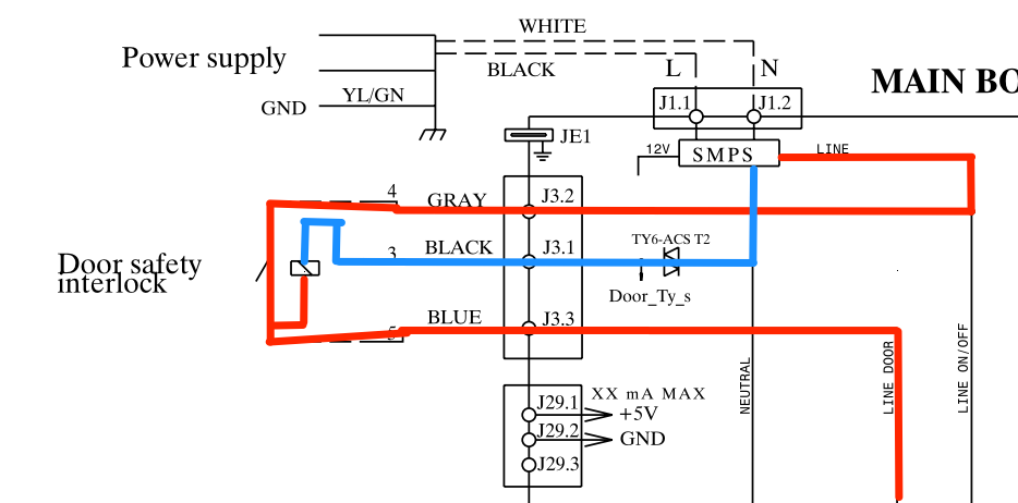
The circuit we're interested in is the one labelled Door safety interlock.

Screenshot 2023-11-30 002240.png

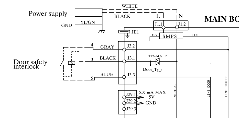
Based on its name and its context within the schematic -- it gates Line to a number of loads elsewhere in the appliance -- this circuit contains the door switch and the door lock. But how exactly does it work? We can assume that the switch is the door switch, but what is that rectangle with the slash through it?

We could sit around and guess, but that's not why we're here. We want to take a look at what we know about this circuit (and about circuits in general) and use that knowledge to suss out what's what.

To that end, let's start tracing our Line and Neutral and see what that tells us!

Screenshot_2023-11-30_002240.png

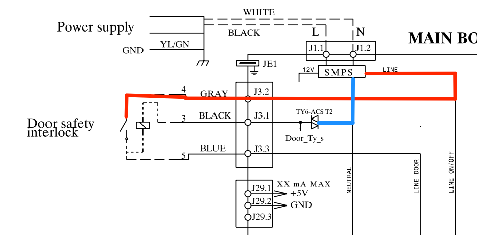
Here's the state of the door safety interlock circuit with the door switch open (as drawn). We're also looking at it with the triac open -- that's the symbol with the two triangles where the blue line ends, in case you're not familiar with the schematic symbol for triacs (more about triacs in this post).

Right away, this should tell you something about that mysterious rectangle with a slash through it. Is that rectangle supposed to represent a switch or a load?

If you answered load, you're correct! Think about it: if that rectangle weren't a load, then when both the door switch and the triac are closed, you would have a dead short from Line to Neutral. Big sparks, no good. A circuit would never be designed to create a short in normal operation. So that rectangle must be a load. More specifically, the only thing it makes sense for that rectangle to be is a door lock solenoid.

Screenshot_2023-11-30_002240-4.png

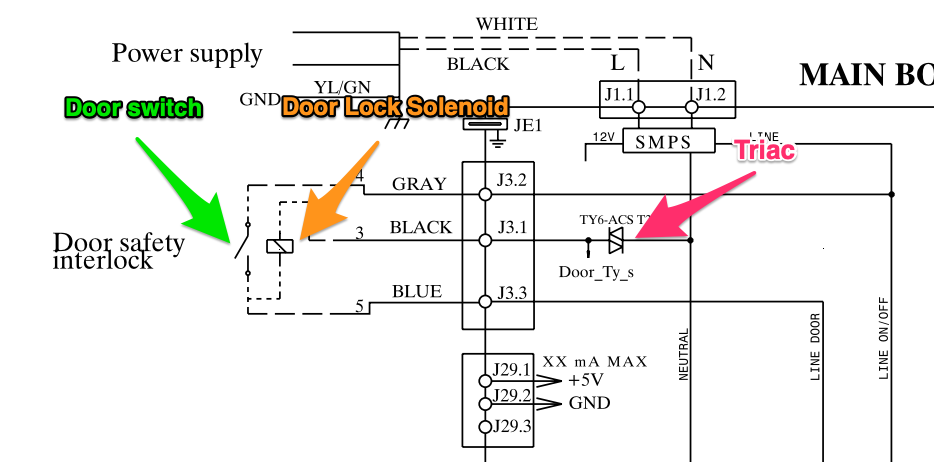
Why do we assume a door lock solenoid? Because we know that there must be a door lock present in this front-load washer. That's a necessary component to keep the customer from opening the door during a cycle and dumping water all over their floor. And where else would the door lock be than in the door safety interlock circuit?

With this assumption, we can take a look at how the circuit must operate.

First, what happens when the customer closes the door?

Screenshot_2023-11-30_002240-3.png

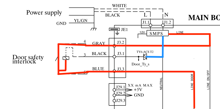
Now that door switch is closed, allowing line to reach loads elsewhere in the machine. But notice that the control board still has to close that triac to complete the power supply to the door lock solenoid. That makes sense, because the control would want to first sense that the door is closed, then actuate the door lock once a cycle as started.

Like so:

Screenshot_2023-11-30_002240-2.png

With both the door switch and the triac closed, we now have 120 VAC pushing electrons through that door lock solenoid. The electromagnetism of the solenoid will actuate a plunger (not shown on the schematic, probably since it's a mechanical piece) which will hold the door shut. And once that plunger is in place, the control board will open that triac once more, cutting off Neutral to the solenoid. Just a short pulse of power is required to lock or unlock the door.

This is a classic case of using our functional understanding of circuits to work around a lack of information. By knowing how electricity, circuits, and loads must work, you can make logical deductions about circuits even when everything isn't explicitly laid out for you.

Want to step up your circuit mojo to the next level? Check out the Core Appliance Repair Training course over at the Master Samurai Tech Academy.

  • Like 3
  • Thanks 3

8 Comments


Recommended Comments

This is why reading schematics with understanding is so important. If I don't know how something works, I surely can't understand how it breaks, and I'm reduced to a PCM. I have seen appliance training competitors sneer at the electrical/electronic training of the Samurai courses. They tend to tout hands-on, but troubleshooting isn't done by having a massive index of "what I've seen before." It is dealing with what I haven't seen using logical steps. Appliances may be electromechanical but are becoming more "electro" than mechanical.

  • Like 8
Link to comment
  • Team Samurai
Samurai Appliance Repair Man

Posted

On 11/30/2023 at 5:15 PM, williamg1916 said:

I have seen appliance training competitors sneer at the electrical/electronic training of the Samurai courses. They tend to tout hands-on, but troubleshooting isn't done by having a massive index of "what I've seen before." It is dealing with what I haven't seen using logical steps.

Excellent comment and observation, @williamg1916, thanks for posting that.

My translation of what these PCM "trainers" are saying, "I don't understand electricity, circuits, or even how to troubleshoot. So instead of learning these things, I'll mock what I don't understand and those who do because I'm a certified lazy ass." And some percentage of equally lazy and weak-minded idiots will believe their BS.  

  • Like 3
Link to comment

@Son of Samurai, hello wondering if you explain something to me, being the slow learner I need some understanding about the L1 going to the SMPS now that I understand PS is power supply, I see on the left it says 12V and then the line out is called LINE if the diagram did not say LINE how do I determine the voltage is AC or DC out by  continuing on the circuit or is there something I should know from MST. While your explanation makes 100% sense, I don't understand where the 12V DC is going or doing. I can see it is going left and down but in another situation am I looking for signs or is this an experience thing. Thanks

Link to comment
  • Team Samurai
Son of Samurai

Posted

1 hour ago, dfphoto said:

@Son of Samurai, hello wondering if you explain something to me, being the slow learner I need some understanding about the L1 going to the SMPS now that I understand PS is power supply, I see on the left it says 12V and then the line out is called LINE if the diagram did not say LINE how do I determine the voltage is AC or DC out by  continuing on the circuit or is there something I should know from MST. While your explanation makes 100% sense, I don't understand where the 12V DC is going or doing. I can see it is going left and down but in another situation am I looking for signs or is this an experience thing. Thanks

SMPS stands for Switched Mode Power Supply. Its job is to convert the 120 VAC input from the wall outlet into DC. It usually also does some EMI suppression to clean up the power supply and protect all the components in the appliance.

The 12 VDC is the voltage supply for the board and its DC loads. That’s why you see it just disappear — that voltage is going into the unshown internal circuitry of the control board. We know that it’s DC voltage because the function of the SMPS is to produce DC from AC.

As for Line and Neutral, those are terms used specifically for AC power. So just from those labels, we know that those lines are for AC, not DC.

  • Like 2
Link to comment

okay @Son of Samurai so in the future there will be something that indicates L1 from a SMPS the 12VDC into the unknown really throws me less thanks you and your dad... eventually I will get most of this! Thanks again...

  • Like 1
Link to comment

Great stuff as always.  When you apply/use the processes you have learned from these courses, no job is really too hard.  I appreciate the FOUNDATION that this school has taught me, it is rare that I get stumped during a call.  Something "new" may delay me a minute, but it doesn't take long to identify the actual issue, test my theory, confirm and then get the customer back up and running!  Many thanks for the skill-sets Team Samurai!! 

  • Like 2
Link to comment
×
×
  • Create New...