.png.f1622b6167220d8c8c781a7c863c9adb.png)
Testing HSI Ignitor Amps at Low Voltages

Entry posted by Rhubarb Tau in Science Try-Its!
1,064 views
I posted this in reply to a Tech Forum post (linked below), but thought I would cross-post here to keep track of it, as well as to have a place to post any follow up testing
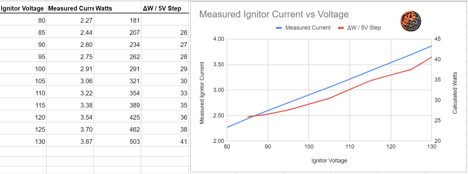
I did a quick test of Hot Surface Ignitor amps at different voltages, and what I measured was way more linear than I expected. See graph below. I used a variac to vary supply voltage to a brand new Robertshaw 41-205 rectangular HSI ignitor. I measured the ignitor current at 5V steps after a little settling time until the current reading looked stable. Not the data I expected, but there you go. Might be interesting to repeat with a well-used ignitor, or with a more accurate current measuring setup, like multiple wire turns through the clamp meter or with a current shunt.
It might also be interesting to include a safety valve in the circuit to see the thresholds where the valve actually pops open, though I suspect the safety valve amp threshold would be relatively independent of supply voltage (since the voltage drop across the valve bi-metal is such a small fraction (~3%) of the supply voltage, seems like fluctuations in supply voltage would have very slight effects on bi-metal heating)
When looking at the graph, note that the red line (Relative change in Watts per 5V change in ignitor voltage) is somewhat artificially scaled to accentuate the slight non-linearity in the data. The measured data is shown in the blue line (measured amps). The red line is a bit of a contrived parameter, and is just calculated by watts at a given voltage minus watts at 5V less than that voltage, basically showing how the slope of the blue line changes with voltage
Edited by Rhubarb Tau
-
.png) 5
5

0 Comments
Recommended Comments
There are no comments to display.