Jump to content
Click here to check out our structured, online appliance repair training courses for rookies and experienced techs.

FAQs | Repair Videos | Academy | Newsletter | Contact


Appliance Repair Tech Tips

  • entries
    220
  • comments
    728
  • views
    149,850

Voltage Dividers and how Control Boards Read Thermistor Input


Son of Samurai

2,626 views

We're all familiar with how thermistors work: their resistance varies with temperature, which in turn varies the voltage drop across them. The control board then reads that voltage drop and determines the sensed temperature based on that.

But those with a bit of basic electricity knowledge might scratch their heads a bit if they think about this. Thermistors are almost always drawn on schematics such that they aren't in series with anything else -- it gets its 5 VDC supply and DC ground directly from the control board, with no loads between. And a single load in a circuit will always drop all the voltage supplied to it, regardless of its resistance.

So how is it possible that the voltage drop across the thermistor changes with its resistance? Well, the truth is that there's more going on here than we're shown on most schematics, all built into the control board.

This image shows the parts of the circuit that are built into the circuitry of the control board and explains how it works.

Screen Shot 2021-07-06 at 11.50.44 PM.png

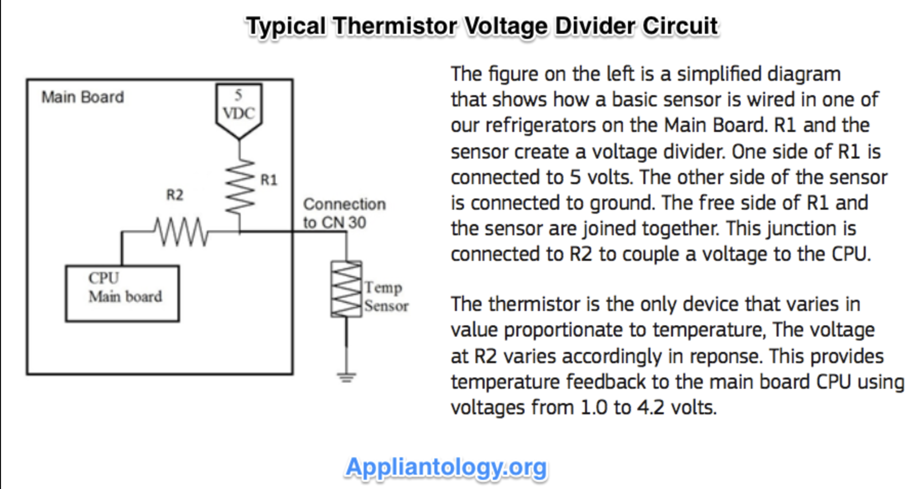
Essentially, the control board is acting just like your voltmeter when you measure across a load. It has one "lead" connected to the hot side of the thermistor, and another "lead" (not shown in the picture) connected to ground, which is an EEP for the grounded side of the thermistor.

Related post: Are thermistors interchangeable? 

Want to learn more about the underlying technologies common to all appliances? Click here to check out the online Core Appliance Repair Training Course over at the Master Samurai Tech Academy.

  • Like 6
  • Thanks 1

4 Comments


Recommended Comments

  • Team Samurai
Samurai Appliance Repair Man

Posted

Just to add a couple of clarifications: In this configuration, the resistance of R2 is much, much greater than the resistance of R1. In other words, R2 >> R1. Where R1 has a resistance on the order of k-ohms, R2 has a resistance on the order of M-ohms.

R2 is called an "isolating resistor" and functions just like the high input impedance of your meter when set on VAC (typically 50 M-ohms for most modern DMMs). R2 enables the voltage sensing circuit on the MICOM board (which functions exactly like the voltage sensing function in your DMM) to read the voltage drop across the thermistor without loading down (i.e., drawing significant current from) the thermistor circuit 5 VDC power supply. (you can learn more about loading down in DC circuits in this video). 

The thermistor's temperature-resistance-voltage drop specifications are stored on the board. The MICOM is programmed to convert the voltage drop measured across the thermistor to a temperature.

  • Like 3
Link to comment

So, this is basically a parallel circuit. The voltage drop across R2 or circuit (which is what the Micom is monitoring) should be the same as the voltage drop across the thermistor.  

Link to comment
  • Team Samurai
Samurai Appliance Repair Man

Posted

1 hour ago, David C said:

So, this is basically a parallel circuit.

Not quite. R1 and the thermistor form a voltage divider circuit. R2 and the MICOM are parallel to the thermistor but R2 is sized very large so that it doesn’t affect the voltage divider circuit. To understand how voltage dividers work, you have to understand voltage drop across loads in series (R1 and the thermistor, in this case). 

As I explained above, R2 is sized very large so that it draws hardly any current from the circuit. That's why it's called an isolating resistor. It is equivalent to the voltage drop in your meter when you do a voltage measurement on the VAC or VDC setting (vs. on LoZ, the input impedance is low so there is significant current draw). Whenever you measure voltage across a load with your meter, your meter is parallel to the load but, on VAC or VDC function, have such high input impedance that they only draw micro amps from the circuit. 

In this example, R2 IS the input impedance to the voltage sensing circuit in the MICOM (again, it functions the same way as the voltage sensing circuit in your meter on VAC; in fact, you could just replace MICOM with DMM on VAC or VDC setting and it functions the same way). 

Since there is minuscule current through R2, the resulting voltage drop, given by E=IxR, will be minuscule as well. Especially in comparison to the voltage drop across R1 and the thermistor. The MICOM, together with R2, is measuring the voltage drop across the thermistor, not across R2. 

  • Like 3
Link to comment

Thank you for taking the time to explain this out.  That helps a lot.  Its hard to admit, but I don't think I had put it together that M ohms where mega ohms and that greater resistance reduced current.  


  • Like 1
Link to comment
×
×
  • Create New...