
How to Identify DC Power Supplies in Appliance Schematics

Entry posted by Son of Samurai in Tech Talk
3,124 views
While all appliances use the same fundamental technology, their manufacturers often talk about them using different terms. Let's talk about DC power supplies and how not to get tripped up by the different terminology used there.
First off, the very basics. Just like in AC, any DC circuit needs two legs: the voltage supply, and the return. The return is called Ground in DC. Don't let that confuse you -- DC ground is NOT AC ground-- they are electrically distinct and separate. Ground is to DC as Neutral is to AC. DC Ground is the return path for the DC current, and without a valid DC Ground, you don't have a complete circuit.
That's all pretty simple. The tricky part comes in with how manufacturers call out their DC voltage supplies and DC Grounds. Let's walk through some examples taken from real-world schematics.
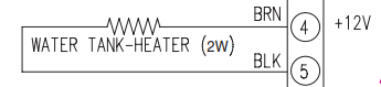
Let's start simple with this water heater. How can we tell that this is a DC load? Well, it doesn't call it out explicitly as that, but it doesn't have to. You can see that pin 4 is labelled as +12V. By identifying the polarity of the voltage with the "+" sign, they're telling us that this is 12 VDC.
But what about the Ground? Well, in this case, they're not even bothering to label the Ground, because it's obvious that the other side of the power supply at pin 5 must be Ground. So this is one way that a DC power supply could be presented.
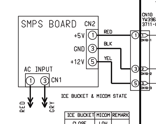
In this board's power supply, you have the DC Ground explicitly called out as GND -- you'll see that a lot. You also have two different DC voltage supplies -- a 12 volt one and a 5 volt one. Nothing unusual there for a board's power supply. They usually use 5 volts to power their logic circuits and/or sensors, and 12 volts to power their DC loads.
Here's another example showing a board with a slightly more complicated power supply, but you see that the same principles apply:
Same sort of thing going on here -- Ground called out as GND, and the voltage supply pins called out with how much DC voltage they're carrying.
Next up:
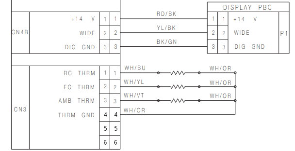
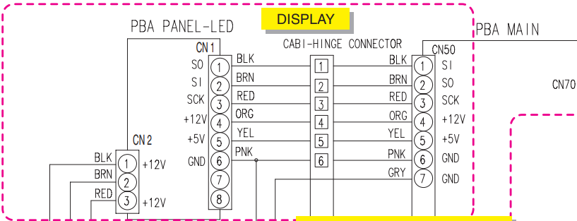
We've got a couple things going on here. Up top, you have a connection between a main control board and a sub control board -- a display board, in this case. You've got a 14 VDC voltage supply to the display board which is typical, but take a look at pin 3. That's our DC Ground, but they're calling it out specifically as DIG GND. That most likely means "Digital Ground", as it must be part of the digital data communications between these two boards.
Consequently, pin 2's confusing WIDE label refers to data communications. That wire is carrying digital data pulses, in a specific data protocol called WIDE, that allow the boards to communicate with one another. Reminder: "data" is simply a 5 VDC supply being switched on and off at specific rates producing pulses of voltage.
Another one for you -- this time, I've marked it up a bit so you can follow what's happening a little better.
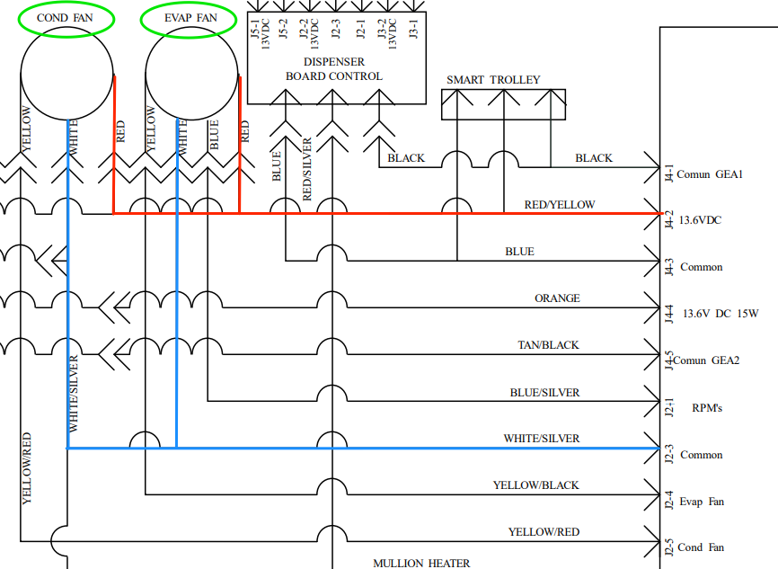
There's a lot going on here, but we're just focusing on the power supplies for the condenser and evaporator fans. They're DC fans, as you can tell from their 13.6 VDC power supply. What you'll also notice is that nothing is called out as Ground or even GND. That's because there's another term that gets used for DC Grounds a fair amount: Common.
Different word, but it refers to the exact same thing. In this schematic, Common is our Ground. Simple enough!
Last one, and it's a doozy. Lots going on here.

Check out that DC evaporator fan circuit. See that VCC? That's a rarer, more esoteric term from the world of electronics, but all it is is another way of referring to your DC voltage supply. There's no difference between the +12 VDC supplies you've seen in previous examples and this one. They just decided to label it with VCC in this schematic.
Another important thing to point out: you see how just below the evap fan circuit, you have a "VCC compressor"? Well, confusing as it may seem, that's not the same VCC. When we're talking about compressors, VCC stands for "variable capacity compressor". They just decided to use the same acronym to refer to two different things on the same schematic! It's like they want to confuse us... But now that you're aware of all these different bits of terminology, you won't be fooled again!
Want to learn more about reading schematics so you never get tripped up on a troubleshoot again? Click here to check out our Core Appliance Repair Training Course over at the Master Samurai Tech Academy.
-
.png) 8
8
-
 5
5
-
 1
1

2 Comments
Recommended Comments