
Troubleshooting a Top-Load Washer Motor that Hums and Doesn't Run

Entry posted by Son of Samurai in Tech Talk
2,988 views
I've got another scenario for you, taken right from the trials and tribulations of an Appliantology tech. Here's the situation: you're working on a top-load washer, and whenever you try to run a cycle, the tub doesn't move and the motor just hums.
Right away, we have a decision to make: do we go ahead and tear apart the machine to take a look at the wash motor? After all, there are a number of mechanical failures that could cause these symptoms. Maybe we should just go ahead and get our hands on it...
But wait -- what if there are easy tests we could do before we get into all of that disassembly? And guess what -- there are! Let's take a look at the schematic and see what we can do.

We've got a few things going on here. First off, all of those bold, dark lines and switches are internal timer wiring and timer contacts.
Second, notice how you have three windings in the motor. This is nothing unusual. S is the start winding, L is the low speed winding, and H is the high speed winding.
So we see the circuits, but how do they actually work together? Which of those washer windings run when in the cycle, and which timer contacts are closed at the same time? For that kind of information, we look at the other page in the tech sheet with the timer chart.
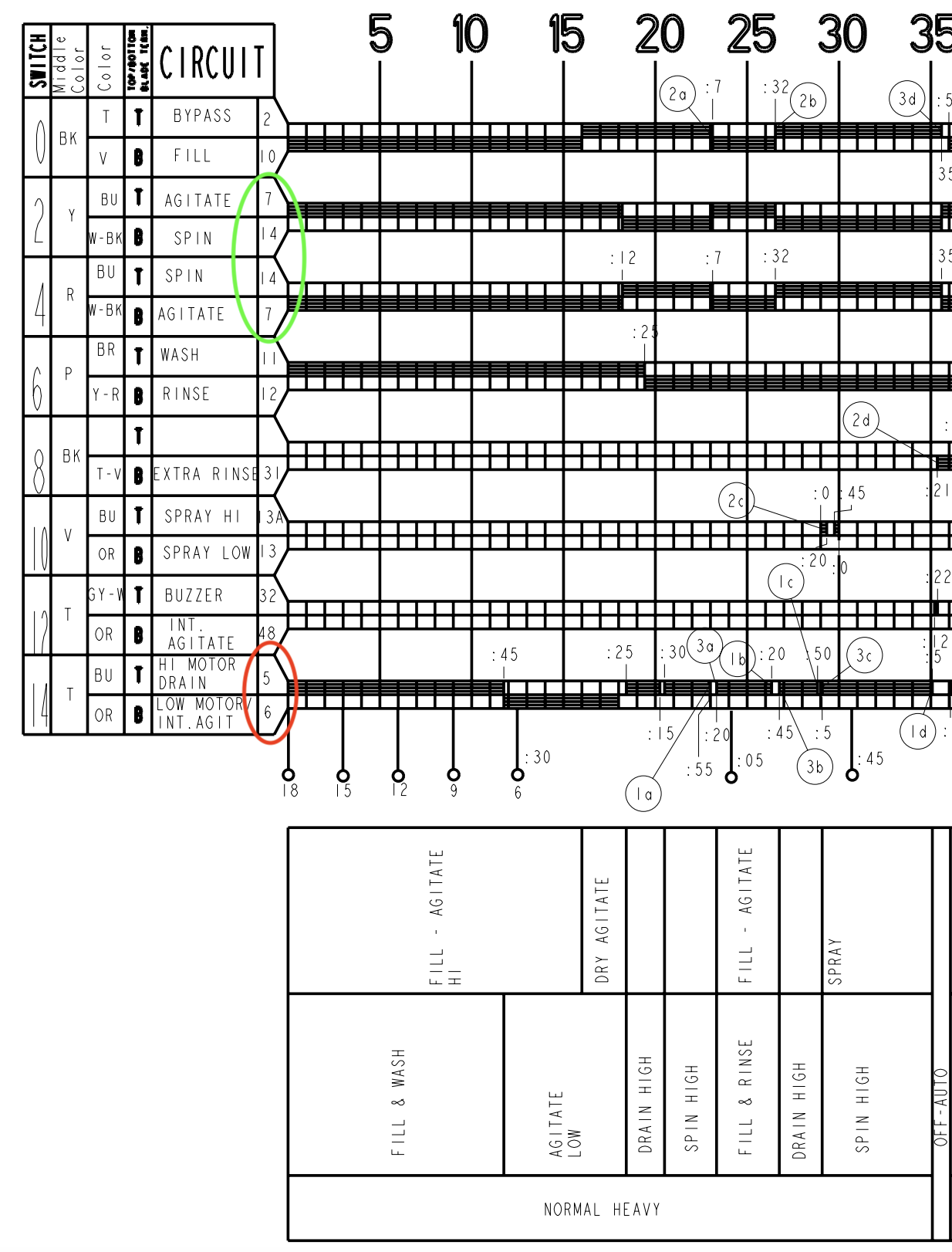
You'll notice that the numbers in the "circuit" column match up with the numbers used to label each timer contact switch on the schematic. Of particular interest to us (since this is a motor issue) are contacts 7 and 14, circled in green, and contacts 5 and 6, circled in red.
Following the row started by each of those numbers, you can see from the black boxes in the chart which switches will be closed when. Using this knowledge, we can now figure out how the circuit should look in different conditions.
For example, during spin, contacts 5 and 14 would be closed. So during startup, the circuit would look like this:
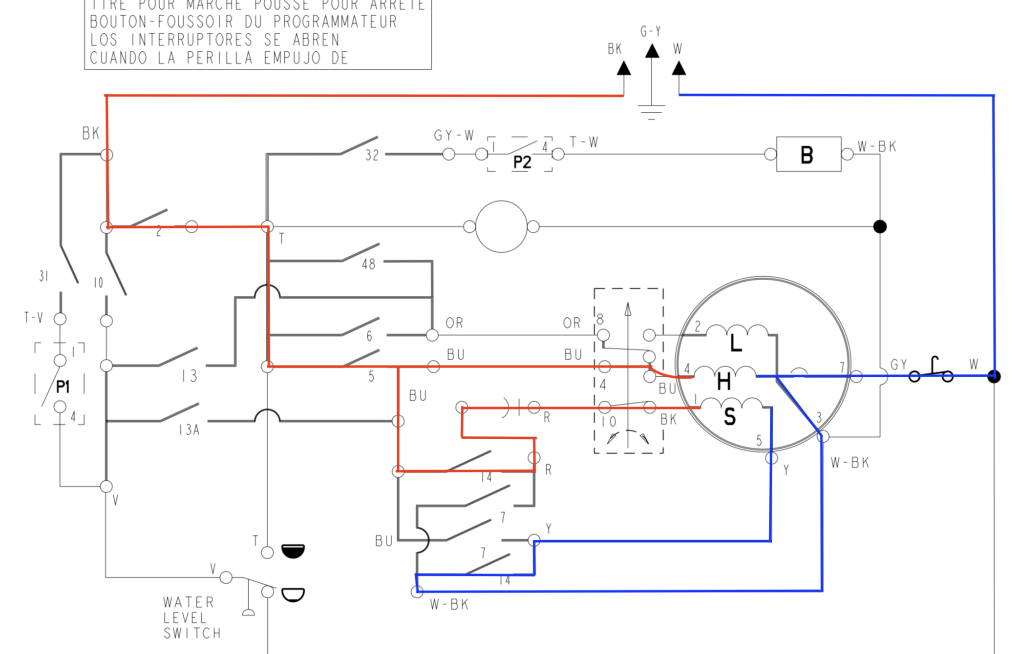
This is the circuit if it were working properly. After a few moments of running like this, the centrifugal switch would open, removing line voltage from the start winding and leaving only the high speed winding energized.
But what would happen if, say, the contact 14 switch providing line voltage to the start winding were to get stuck open? In that case, the circuit would look like this at the start of spin:
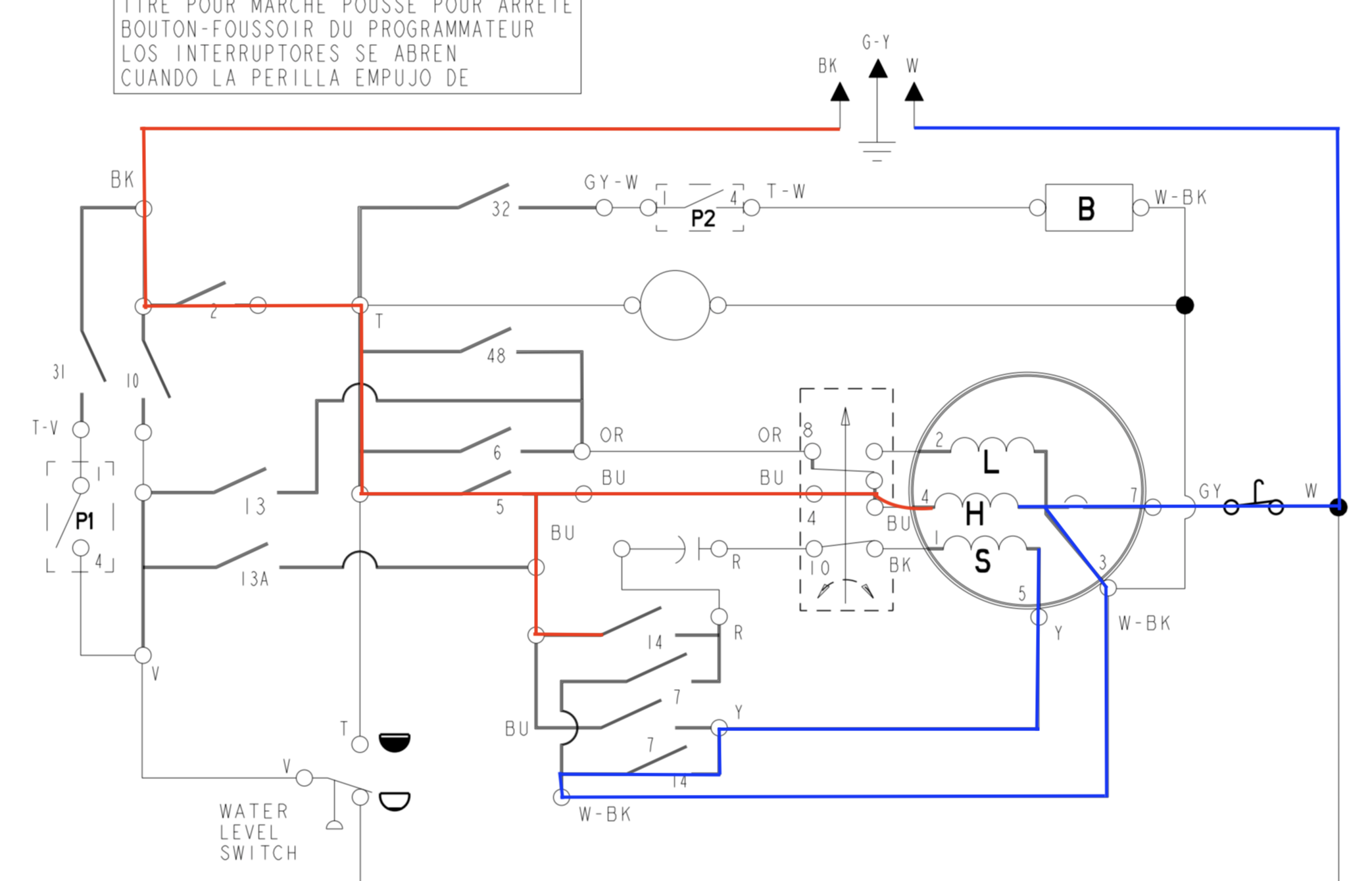
Aha! If this scenario were to happen, we would get exactly the symptoms that we're experiencing. The high speed winding is getting power -- hence the humming -- but since the start winding is never energized, the motor can't actually get going from a dead stop.
Knowing this failure mode, it's a stupid easy thing to test for. All we need to do is run a cycle and check voltage at the timer contacts in question to make sure they're closing properly. If you read voltage across contact 14 (Blue to Red) = timer contact stuck open = new timer. These voltage tests can be done right from the timer, with no additional disassembly required. If your voltage tests show everything is in spec, only then do you need to disassemble to investigate further.
And in case you're wondering, a failed timer was exactly the cause of the problem the tech found in the real problem I drew this little case study from.
This is exactly the kind of schematic know-how and troubleshooting techniques that we teach in the Core Appliance Repair Training course over at the Master Samurai Tech Academy. Click here to check it out and attain appliance repair mastery.
-
.png) 10
10
-
 2
2


1 Comment
Recommended Comments